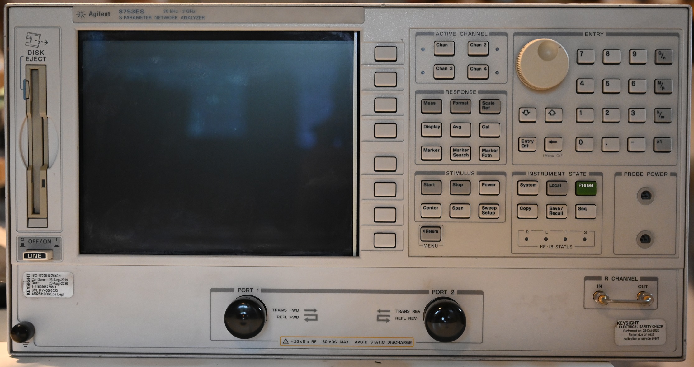
Repeating my past act of acquiring large articles of Agilent kit, today it’s an 8753ES. This particular unit has been sitting faulty in the stock of a local IT equipment recycler for some time, for a rather lavish price considering. After patiently waiting for price expectations to soften, it’s now mine for a very reasonable sum.
Buying an instrument like this from such an outfit has its pros and cons. On one hand, they don’t know what it is, how to test it, or how to price it. On the other hand, in the case of a faulty unit, myself as the purchaser is completely in the dark as to what condition it is in. At least I got to see inside it before handing over the dosh.
Superficially the fault presents its self as the screen not turning on. I went through all of the power supply tests, all OK there there, so then I whipped off the bottom cover to look at the A9 CPU board which is most likely to be at fault.
Sure enough, the red LEDs of death are illuminated:
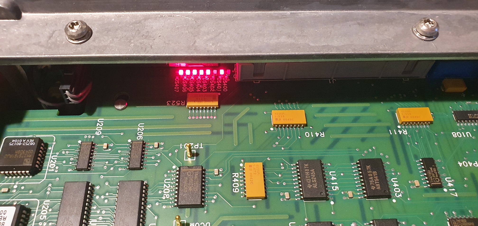
There is nothing in the service manual which gives any clue as to what this particular pattern means, other than stating “Replace the A9 CPU board”.
By my rough estimate, the A9 CPU board accounts for around 1% of the original cost of the instrument. Today, a working used sample is worth a third of the value of an entire used instrument. This would imply that it’s a likely item to fail, and that people aren’t having too much luck repairing them, despite it being one of the most repairable parts.
And that is likely because of the difficulty of diagnosing faults. The comprehensive built-in software diagnostics normally relied upon to repair these instruments its self has failed. I felt the best place to start was to remove the board from the instrument and power it on the bench stand-alone. This’ll make things a lot more practical and reduce the risk of damaging the rest of the instrument. Unfortunately there is no pinout for the power connector (J2) in the service manual.
From a bit of poking around with a multimeter I find the relevant connections. Pins 1-8 are GND, and 9-16 are +5V. When I first powered it up on, all eight LEDs are illuminated, instead of 6. It was fairly obvious that this was because the processor was still in reset. Reset was found to be NAND’d through to U120, with one input leading to the CPLD U316 (I presume this is the suicide register), and the other input appearing at pin 20 on J2, this’ll be the “Power good” signal. I connected it to my test PC power supply’s power good signal, and tried again.

This time, it looks better. I have the same 6 LED error code I had when the board was in the instrument.
I now know that the processor is working, executing a little bit of the startup code, but crashing out for some reason. I also know that it’s crashing very early on as only two codes are seen before it stops. This display is able to present up to 255 error codes and from other reports does cycle through many before a successful boot.
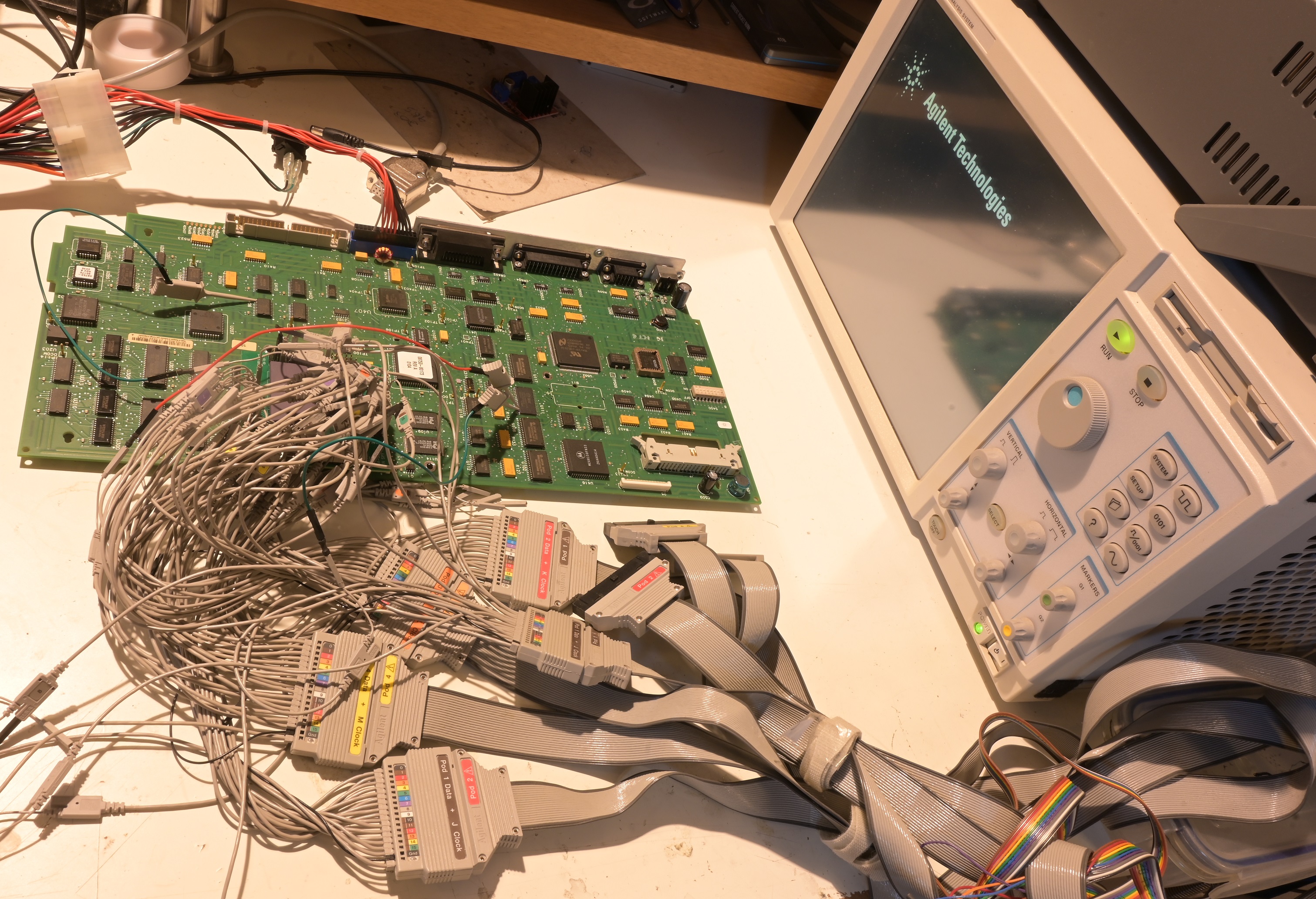
To get a better understanding of what’s going on, I’ll be drafting in this instrument’s distant cousin: the Agilent 16702B. It’s worth pointing out that at the time of writing, such an instrument can be had for less money than a working A9 CPU Board, making this an attractive endeavour.
But how to hook it up? There are no bus analysis connections on this board. Either Agilent’s software developers are so talented that they never had to debug their Boot ROM, or, perhaps there was a prototype of this board with Mictor connectors on it?
Perhaps they had a “Pin Spy” which sits between the CPU and the mainboard. I found some pre-made but for quite a high price. Since this is such a simple thing to design and build, I whipped up my own and sent it off to be fabricated. There is a link to download the design files for this at the bottom of this post.


After constructing and installing the pin spy, I can now hook up the analyser. The CPU in this instrument is a Motorola 68040, a 32-bit processor with a large, fully usable 4GB address space. Because I know nothing about how this board is designed, I want to do a full bus analysis on it, which will require at least 64 channels, 70 or so including control signals. Being able to analyse the entire bus in a single time domain allows me to quickly put together a picture of how the board is designed.
I started off by connecting the D0-31, A0-31, TS, TA and R/W signals. This is enough to give me quite a good overview of the startup process. I then connected another probe to pin 11 (CP) of U406, the latch which drives the diagnostic LEDs. To help myself cut through the reams of irrelevant bus transactions, I put a breakpoint on the falling edge of this signal combined with the data pattern 0x05000000 (the error code is 5 according to the LEDs themselves) and bingo. I’m now at the start of the code which is failing.
Scrolling through the bus transactions I quite quickly see that the CPU is trying to write 0x55555555 to address 0x30000000 but reading back 0x55551555. Bingo, some kind of pattern test, which is clearly failing. But what is being tested? Whatever it is, it’s something with a 32-bit interface and there aren’t too many of those on this board.
My first suspicion was the DRAM, as this is a likely part to fail, so I connected some of the control signals into my session but they were inactive, so not the DRAM in this case.
I them moved into the bus interface to the DSP. This consists of a set of four 8 bit dual port registers (U311, U308, U305, U300) which could be tested in this way. Nope, the control signals of these aren’t active either. There must also be some steering logic on the other side of this as the DSP only has a 16-bit bus, but this isn’t relevant to look at the minute.
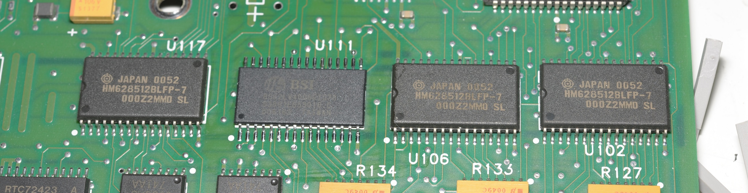
I moved onto the SRAM. Now, I think I’m onto it. The SRAMs were indeed responding to the write to 0x30000000, so now just a case of working out which chip was suspect. From the pattern it is clear that it is bit 1 in question, so I attached probes to bit 0 and 1 of each chip and quickly narrowed it down to U111.
This is the absolute beauty of having a large logic analyser for diagnosing faults like this, rather than trying to guess what’s wrong by replacing many working parts, wasting money and potentially damaging the PCB in the process, I can instead strike at the one faulty part with surgical precision.
The SRAMs originally fitted are HM628512BLFP-7. I don’t have any of those to hand however I do have some which are compatible, albeit not quite in the right package.
When I next powered it up, bingo, I’m no longer stuck on error code 5. Instead the board is cycling through many new codes which I have not yet witnessed. Time to put the instrument back together.
The CPU board cycled through all of the POST codes, and, all cleared!. It’s alive!

You might notice this smith chart doesn’t look right for an open S11 measurement. There is another repair article for this instrument here.
Posted in Repair / modification, Test equipment
Hello!
My 8753E 6GHZ didn’t scan the baseline after it was turned on, but after pressing “SCALE–AUTO SCALE”, it showed that there was a baseline, but the noise floor was very loud and there was interference and jitter. What kind of malfunction is this? Hope to give some ideas.
steven
from CHINA
I saved one of these from the skip.
Powers on but no Display.
I can select between channels and preset so not totally dead.
Trying to dig out an old VGA monitor to try that.
Usually the displays are fine. It’s the backlight and connectors that go bad. Removing and reattaching the white display connector from the inside will allow the display connection to be fixed in 9/10 cases. As for the backlight, issues vary between the lamp and the inverter circuitry. If it’s the inverter, an inexpensive LED conversion usually solves the issue for $20.