EDIT: Looking for information about the Widescreen Philips pattern?
If you have seen one before, the PM5644 is unlikely to have generated it. It is a very old piece of analogue equipment from 1991. With a few rare exceptions most models only generated 4:3 patterns. More likely that it was generated by a PT5xxx series sync generator (first introduced in 1998). Check out my test cards YouTube channel for recordings from them.
UPDATE: I now have a YouTube video covering the PM5644. The remaining information on this page should be regarded as historic.
I also have a video about PT5xxx sync generators:
Introduction
In my recent quest to build an analogue television broadcast modulation setup it occurred to me that I’m going to need a good pattern generator to calibrate the modulator. Two months later and this has now turned into a massive distraction.
So off to the usual place and I’ve got a few new bits of kit to look at.
PM5631 (MP)

The PM5631 is probably most useful for my intended application because it’s easy to pick out a specific pattern to test exactly what I want. This particular one is notated “MP” (multi-pattern). I have not seen any example of a non multi-pattern unit. These appear to have hit the market around 1987/1988 certainly at the time I purchased mine there were units for sale made around this time. Mine is a tad newer dated 1991.

The PM5631 is test equipment, generating up to 100 different simple patterns such as colour bars. There is a YouTube video where someone has cycled through most of the patterns.

I am intrigued as to how these things actually work. The assembly doing the pattern generation is the one in the centre. Fitted to it are four BPROMS and a single EPROM. It appears that all of these, combined with the CPU are somehow cleverly generating a huge number of different patterns with frankly very little ROM space.
The assembly on the left is the sync generator and external sync input. The assembly on the right is the one doing the digital to analogue signal conversion plus luma and chroma mixing.
PM5644

I actually ended up with two of these which both appear to be quite different despite very similar appearance. The PM5644 appears to have been based on the PM5631. It uses the same chassis, power supply, sync board, internal layout and a very similar design approach.
The key difference is that the PM5644’s patterns are mostly rasterised whereas the PM5631’s are simple vector based patterns. The PM5644 has broadcast niceties like a phase locked 1 KHz audio tone generator and a time code input connector.
Unit 1: PAL 4:3 Colour circle
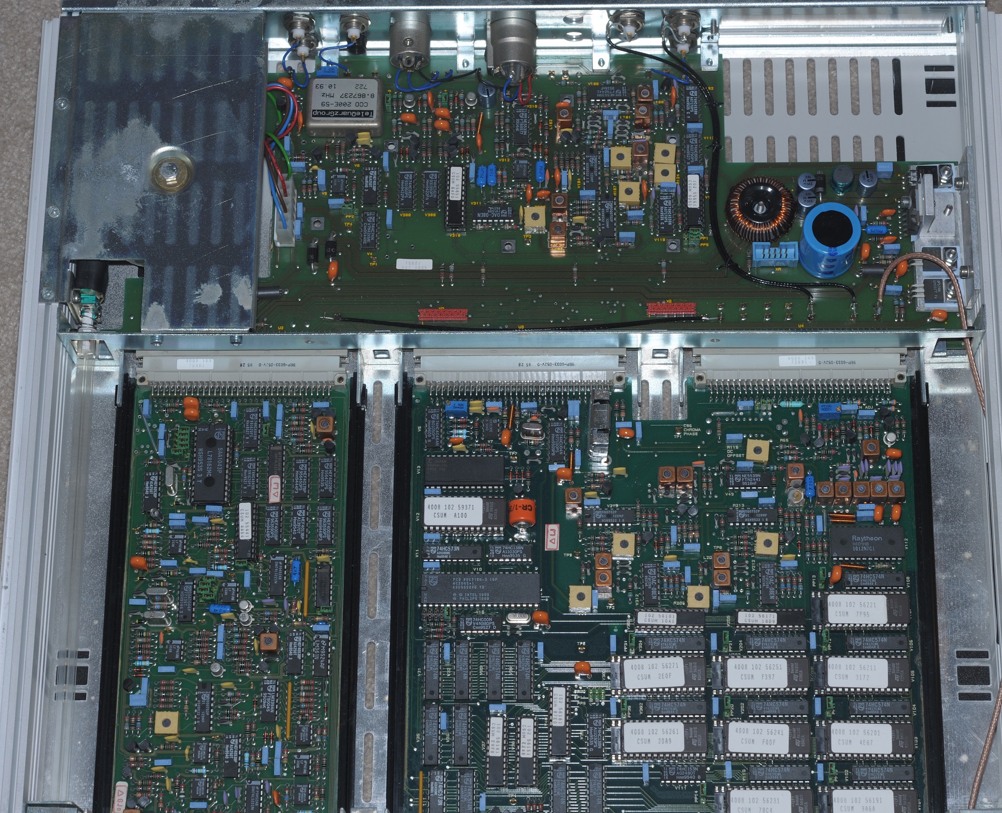
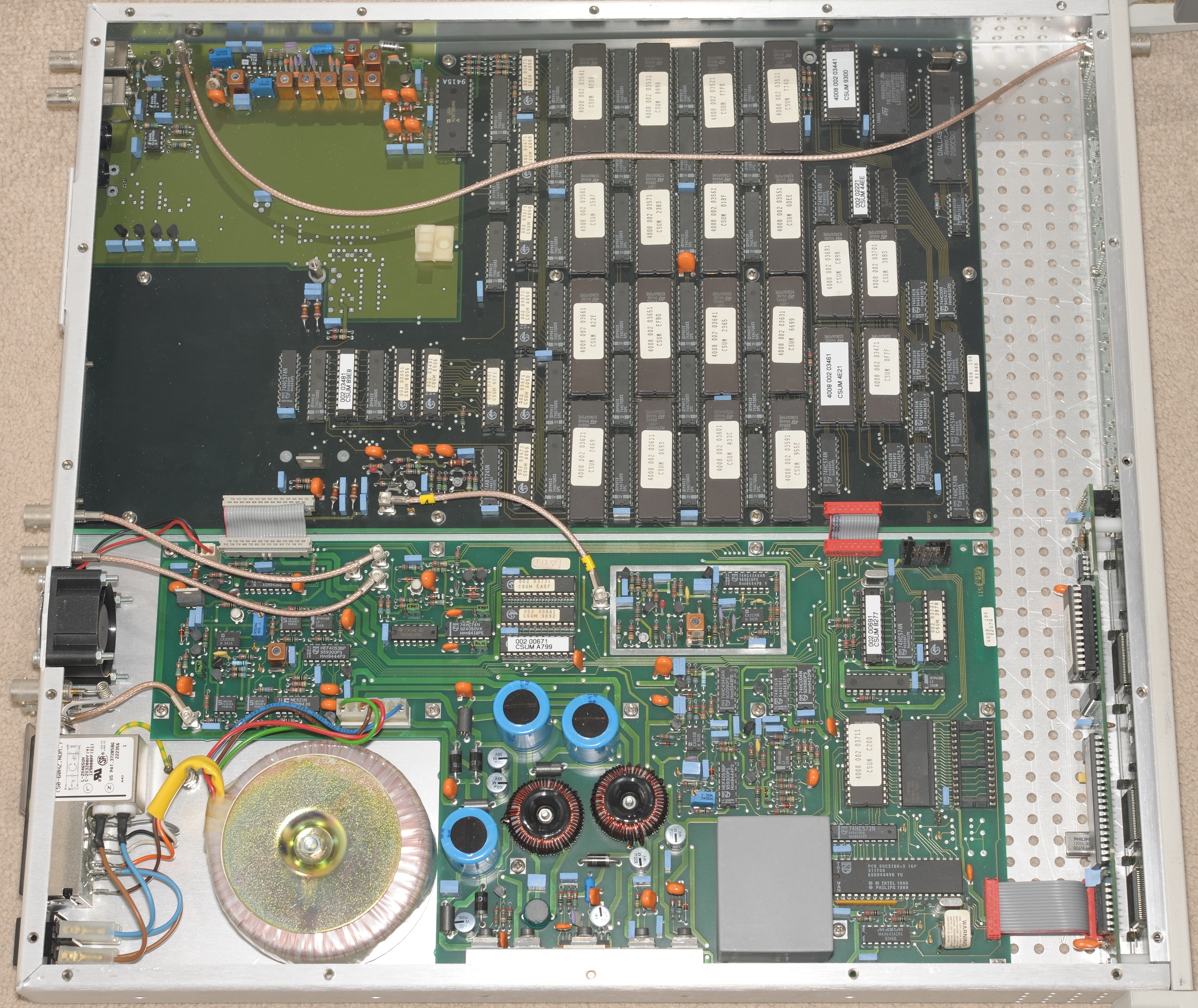
Unlike the PM5631 these units both came programmed with a single complex pattern. This particular unit appears to be the earliest and most primitive design. It has 576KB of pattern ROM and is effectively hard wired for 4:3 patterns typical of the previous generation PM55xx designs. The hardware design assumes that the edges of the pattern are repeating in nature (i.e. it uses sprites). Only the centre is allowed to contain rasterised graphics.
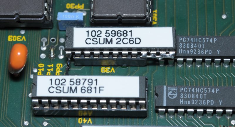
The EPROMs are split into three banks giving a YUV 4:2:2 arrangement (10-bit/8-bit/8-bit) – Luminance (5 chips), Chroma R-Y (2 chips) and Chroma B-Y (2 chips). The three banks of EPROMs are in turn connected to three DACs – Raytheon 1012N7C1 (TDC1012) for the luminance, and two Signetics DAC-08’s for the chrominance. The signals are then modulated into the composite output using a pair of OQ0702P’s (TCA240). Generation of the colour components has to be done separately because these are able to synchronise to a black and burst signal.
There are four known variations of these units:
- PM5644G/00 (PAL)
- PM5644L/00 (SECAM)
- PM5644P/00 (PAL-M)
- PM5644M/00 (NTSC)
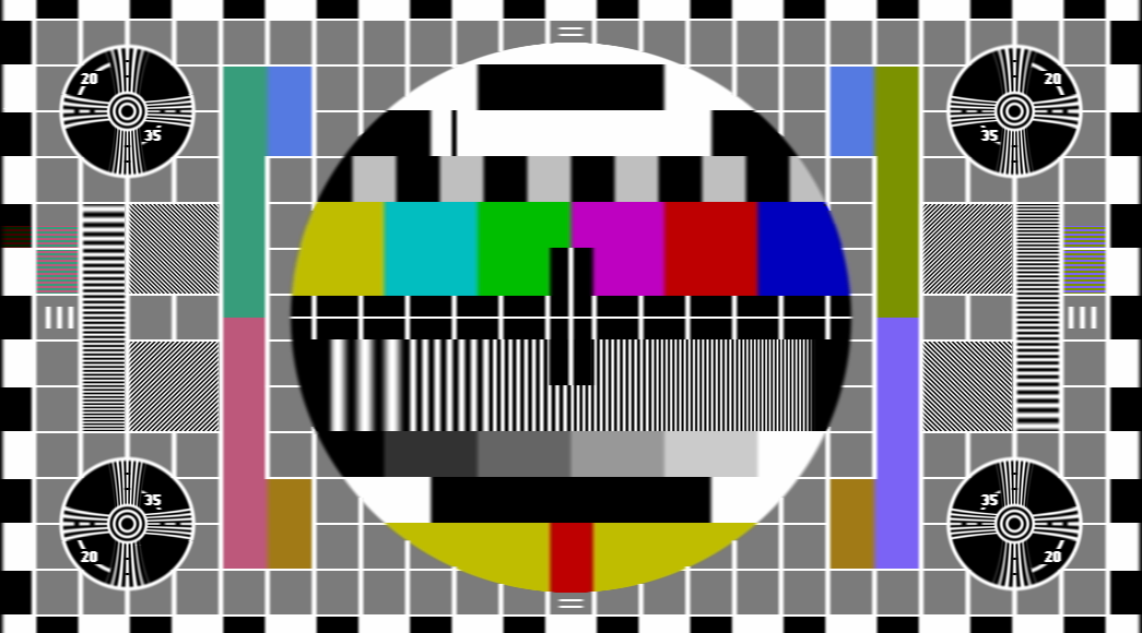
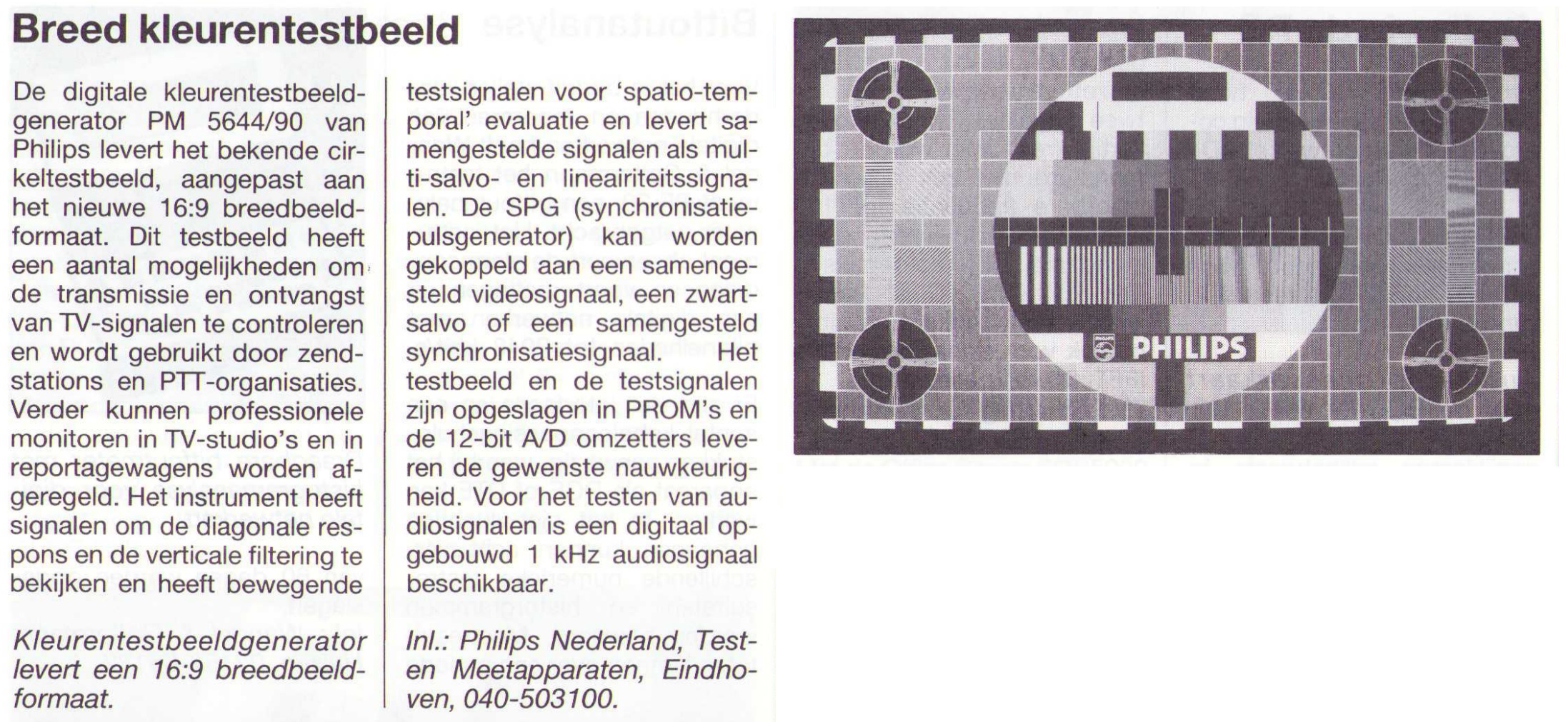
All are programmed with the Philips 4:3 colour circle pattern like the below:

The above pattern is the PAL version. The patterns for other standards are (slightly) different.
The mechanism for programming station text into the black boxes is different for the PM5644. On the PM5544 this was done by soldering a matrix of wire links onto a card installed into the unit.
On these units it has to be done with either the PM8546 logo generator or programming a pattern of the text into the four luminance EPROMs. The advantage is that significantly higher resolution text and graphics are possible than on the PM55xx series where text typically appears quite “blocky”.
The disadvantage is that it requires extra hardware or a computer and specialised software to do it. From looking at a catalogue page (at the bottom of this post) Philips did offer pattern customisation, likely for quite a price.
I’ve partially reverse engineered this unit. There’s a project on GitHub which generates the above image from the pattern ROMs.
Clock cut-outs
Hidden underneath the front panel are a few buttons. I pressed them all in various combinations to see what they did. I turns out there are a couple of options for the appearance of the pattern:


This version of the PM5644 cannot generate the actual clock. The DACs are only connected to the EPROMs which means moving pattern elements are not possible. This has to be done by a separate teletext generator.
This is how it is done with the PM5534 (PM5544 successor) although there was space inside the actual generator for the unit which did this, an item which was sold by Philips. In the case of the PM5644 there was an optional add-on (PM8546) which generates station text and a clock. They may also have used other equipment capable of text overlay, more likely to meet their differing requirements.
There is an image on Flickr showing a real broadcast in this mode. Like almost all Philips circle patterns pictured on the internet it is stated to be “PM5544” but I think that might be incorrect as the 4:3 PM5644 existed in 1994 and the pattern shown in that image is missing the bottom box reflection check which is typical of the PM5644.
Unit 2: PAL “Indian-head”

A very interesting and peculiar unit programmed with this pattern:

It’s a Philips take on the RCA “Indian-head” pattern (monochrome). Popular on the American continent decades ago. My discovery of this pattern is the first image of it that has ever appeared on the public internet. The story behind it is presently unknown. Suffice to say it was probably made to order.
An editor of the Indian-head Wikipedia page notes:
In October 2022, a 4:3 monochrome test card that resembles the Indian-head test pattern was discovered in an EPROM chip of a Philips PM5644 PAL generator purchased by a British television repairman from a European scrap dealer.
(Sure, I’ll take it)
Despite a very similar appearance to the colour circle pattern unit the operation of this unit is completely different. It has 4 MiB of pattern ROM. In addition to having a larger number of vertical samples per line than the other unit (1040 vs approx 700) it can display any rasterised pattern thus is not limited to PM55xx type patterns like the other unit.
Although it is fitted with chrominance EPROMs programmed with nothing but the colourburst it was supplied to me with the chrominance carrier electrically disabled i.e. it does not even produce a colourburst – generating a true monochrome signal.
I cannot find any other documented examples of a PM5644 like this unit. Like the other unit, it is a PAL (G) model. Although there is no known example of it, this design may be one that can accommodate the well known 16:9 colour circle pattern due to its higher line resolution and ability to render arbitrary rasterised patterns.
Unit 3: SECAM Colour Circle

The SECAM unit is of a completely different design to the PAL and NTSC versions. This is because SECAM cannot synchronise at a colour sub-carrier level, thus much of the complexity of the PAL/NTSC designs is not required.
The sync board is a different (simpler) design. All of the chrominance circuitry is omitted too, essentially there is no point in fitting it. Instead Philips modulated the colour subcarrier into the luminance EPROMs likely using the same software tools they used to generate the EPROMs for the PALplus unit discussed later on this page.
Also missing is the black and burst circuitry on the rear, once again, there is no such concept in SECAM.
Another interesting feature on the rear PCB is a 10 MHz TCXO instead of the usual colour subcarrier oscillator. Not sure what this is doing.

PM8546 Logo Generator

Above is a PM5644 with the PM8546 logo generator installed (highlighted in red). It does the same job as the PM5543 teletext generator (PM5544/5534 accessory) but is a lot more advanced. It can overlay text and graphical logos in the top and bottom black boxes, and optionally can overlay a clock. They are typically only installed in units used in broadcast, which unfortunately rarely find their way to the second hand market thus it is unlikely to find a PM5644 fitted with one. I have never seen one myself.

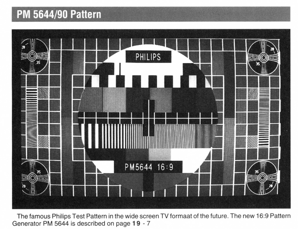
PM5644 widescreen models
It is rather unfortunate to be talking about the PM5644 without also discussing what it is most known for. They are difficult to find because broadcasting over analogue infrastructure was short lived and not done at all in many countries that originally adopted the PM5544/PM5534 or by that time they had around-the-clock programming thus there was no air-time for test cards anyway.
The scarcity turned out to be a pain in the backside. Until now there has basically been no information on the internet about what equipment actually generates the well known widescreen pattern other than “It’s the PM5644” (even though inconveniently all of the units found by enthusiasts only contain 4:3 patterns).
After reaching out to a lot of equipment dealers I managed to turn up not one, but two widescreen PM5644’s. Let’s have a look:
Unit 1: PAL non PALplus

As was to be expected (from looking at the front it it) internally it is almost identical to the 4:3 models. It has a bunch of buttons on the front panel that we don’t see on the 4:3 models. The 4:3 models technically do have a few buttons but they are hidden under the front panel.
The million dollar question – what pattern does it generate?
It has already been pointed out to me by an eagle eyed reader, before I even wrote this, that it’s different to the pattern produced by the PALplus model. Can you spot the differences? Here is a transmission using it from Belgium. The most interesting feature to me is the inclusion of a ridiculous 5.8 MHz grating; something that would never be seen when received on-air. In the PAL B/G system that would end up right in the middle of the NICAM carrier.
You may have seen that in relation to the Indian head unit I speculated that one like this may exist which generates 16:9 patterns. I was correct. This unit, like the Indian head unit has a 20 MHz DAC clock (higher than the usual 13.5 MHz for 4:3 models). It also is loaded with larger 27C4001 EPROMs and is capable of addressing much larger patterns (>576KB) than the 4:3 models. The surprise (!) is that this has been done by post production re-work:
In conclusion I believe the Indian head unit is the final hardware for the 16:9 product. I have since confirmed that it is able to produce the 16:9 pattern without any post-production re-work purely by swapping all of the EPROMs and three PALs. The G/924 unit I’ve shown here is a prototype. It has a bunch of other patterns too. They are not very interesting. I’ll probably details these in future.
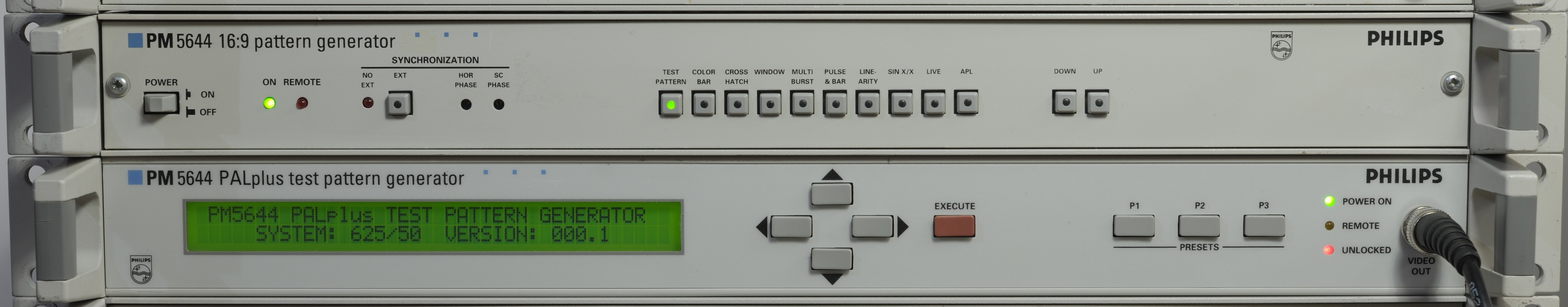
Unit 2: PALplus test pattern generator
As expected as the last unit this one is totally and utterly different to anything I have seen before. It has a s–tload of EPROMs and PALs in it. It took me nearly two hours to dump them all. A couple of interesting points: 1) It does not have any PALplus encoding chips in it. 2) There is only one DAC. I strongly suspect that the entire signal: PALplus, luma, chroma is modulated digitally.
So what pattern does it generate?

That one (almost). I do not have a PALplus capable television to show you this one on unfortunately. I can only view an embarrassingly low quality version in 4:3 compatibility mode. In future I’ll try and find a PALplus TV to view it on.
It also generates this pattern:

Front panel controls
Broadly speaking it has three modes: PALplus, 4:3 and “Custom” which it complains is not available in that particular unit.
Within each mode there is a variety of different patterns, either the colour circle pattern or a bunch of different simple monochrome patterns.
There are some minor options like VITS generation and other PALplus specific stuff i.e. enable/disable helper signals. Finally it has the option to show pre-programmed teletext in the black boxes i.e. “PALplus 16:9” but it cannot be edited.

To make matters more confusing the above image from this magazine shows a pattern apparently generated by the PM5644/85 but actually looking more like the first unit. It may be that they didn’t have an up-to-date shot of the pattern of what at the time was a new product?
More information
Check out my GitHub repository where I keep technical information i.e. manuals, schematics for this type of equipment.
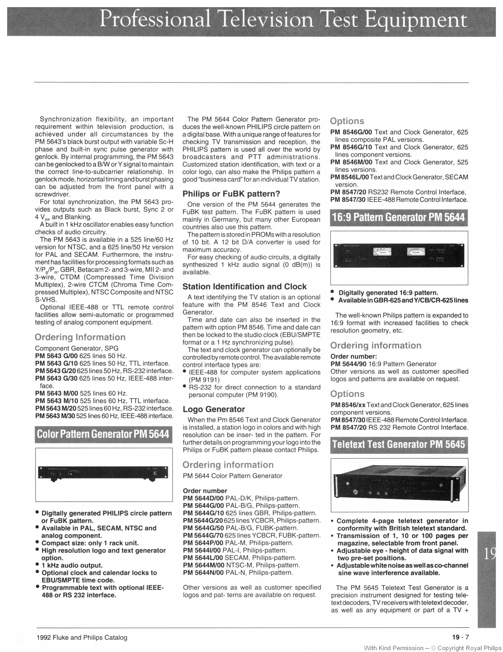
Other options / models
See the catalogue page below:
And finally

Just because it looks like a Philips test pattern, that does not mean the equipment that generated it was made by Philips. By the 1980s it was the wild west in terms of whose equipment generated what pattern. Philips were cranking out PM5644’s that generated Tekefunken’s FuBK pattern and RCA’s Indian head pattern. Consider the above, the “SGPF” from Rohde & Schwarz. It offers the same patterns, and many of the same features of the PM5644. There are many others too.
Posted in Broadcast tech
hi I have a PM 5644 like yours and it generates a monoscope at 4:3 to turn off the clock and the station mark I tried to disconnect some connectors inside and I got the result because I didn’t know the sequence of keys to press for remove it electronically. one question is there the possibility to select the 16:9 format since the Pm 5644 is by nature a 16:9 and not a 4:3? Thank you. Fernando Greetings from Florence. (I’m the one who has pm 5631 that I posted on Youtube.
Hey there. The notion that the PM5644 by nature is 16:9 is folklore. A PM5644 supports whatever pattern(s) it is programmed with at the factory. There are many different SKUs and the units that have been found by enthusiasts to-date are overwhelmingly 4:3. You will be able to select all of the patterns it contains by pressing the buttons on the front panel. You may need to remove the front panel to access them. Don’t be surprised if it has just one pattern – this is the case for most SKUs.
Regarding widescreen – if it supports widescreen it will say so on the front panel (see this image: https://en.wikipedia.org/wiki/Philips_PM5544#/media/File:PM5644_Variants.jpg ).
It is possible to convert a native 4:3 unit to 16:9 however note that this is not a trivial exercise. If you are interested I can help you out with this. Drop me an email. Contact details on the about page.
By the way – can you send a picture of the patterns it outputs, and what SKU is stamped on the back of it?
PS: Do you still have that PM5534? I would love to see a teardown of it.
Matt
I would like a Homemade Philips PM5644 Test Pattern Generator or a Rasberry Pi from Github, and in addition I would like a PM8546 Teletext Logo Generator that displays time and date and station text names.
I would also like to have a PM8546. I don’t have one. As for a Raspberry Pi based project, I don’t personally have any plans to attempt it.
You may have already seen this:
https://www.youtube.com/watch?v=XYgBtGw-Cgc
PT5xxx series does exactly the same thing.
I want to create. Can you recreate the font of the PM8546 using FontCreator?
Interesting project but I don’t know anything about creating fonts. I already dumped some of the PM8546 font. It is on Wikipedia.
I would like to get Philips PM5644 test pattern generator to test it if there is PM5644 test pattern file from Github if available thanks.
https://www.youtube.com/watch?v=BoqWdbcRNuM&t=297s
How to create a new Philips PM5544 test pattern generator as in the video. Do you need a Rasberry PI or use DK Technologies’ PTV files from Github?
I can vouch for such a pattern not necessarily being generated by one made by Philips. Several screencaps taken off air have shown such a pattern as emanated from a Tektronix TPG-625 (with the same type font that was used for color bars and all on their NTSC TSG-170A/D and PAL TSG-271 generators).
Has anyone tried to approximate the type font that was on Philips’ PM 5544 as used on both PAL and NTSC (the latter, most famously in New York in the 1980’s by WNEW-TV / WNYW Channel 5)?
No need to approximate it. An exact rendition of the PM5534 (used by WNYW) font is on Wikipedia.
https://www.youtube.com/watch?v=EQKXckwcGr8
what font in PM5544 of RTSH (Radio TV Shqitar) of Albania?
That is the output of a PM5534. See this: https://github.com/inaxeon/PTV_Preservation/blob/main/PM5534/Docs/PM5534_Brochure.PDF
what name font of PM5534 and i want to download of PM 5534 font?
I have no idea. Let me know if you figure it out!
And is the PM5534 test pattern generator still available for sale?
Sold between 1980-1989
https://www.youtube.com/watch?v=BoqWdbcRNuM&t=298s
Why does a Spanish person who made a video clip of the pm5544 test format on YouTube say it was made with a C++ program?
https://www.youtube.com/watch?v=Cs6oqgIn2bs
PM5544 test pattern of BBTV CH7 (Thailand) and I was in Thailand.
hi I want you to test gear, teardown and fun of Philips PM5644G/00 Pattern Generator in your Matt’s TV Barn in your youtube channel due I was please seen your use Philips PM5644/00 G 4:3 pattern generator and your demostratre PM8546 logo generator.
one question PM5644/00 and PM8546 logo generator was is retro analog and piece equipement in 90s onward and was use various broadcaster in the world. Thatsapat Greetings from Nakhon Ratchasima (I’m the one who has plan to buy and donate PM5644/00 from former engineer in Thailand)