For years now I’ve had a honking big Tandon TM100 360K 5¼” floppy drive which has been screaming out to be used, and there is something I’ve wanted to use it for – on a “go between” PC so I can shunt files to and from my XT era PCs which I tinker around with.
The easiest way to do this is to have, say, a Pentium II era desktop PC on a network, etc – but that’d be a big lump of junk I don’t want taking up space in my cave.
I could also splash out on a Kyroflux, which would let me attach it by USB to a modern machine but Kyroflux being a specialty tool for data recovery, isn’t convenient in my use-case whatsoever because it only works on entire disk images, doesn’t do drag and drop – it isn’t really what I want. If only I could attach it to my Thinkpad 760 – which I can easily network, and has an external floppy connector.
I’ve been pondering this for a long time now, but knew it wasn’t going to be straight forward.
Difficulty #1 – What is the sodding pinout for that connector?

I had previously spent hours searching around for a schematic, spec, any kind of information on this connector but came up with bupkis. I could buy an external floppy for it, bust it open and have it in minutes but in the UK where I live, most 700 series Thinkpads were sold with internal floppy drives, so these are pretty much unobtainable. I’d have to ship one from the US at massive expense.
Given the ridiculous amount of spare time lockdown has created – I decide to do this the hard way.
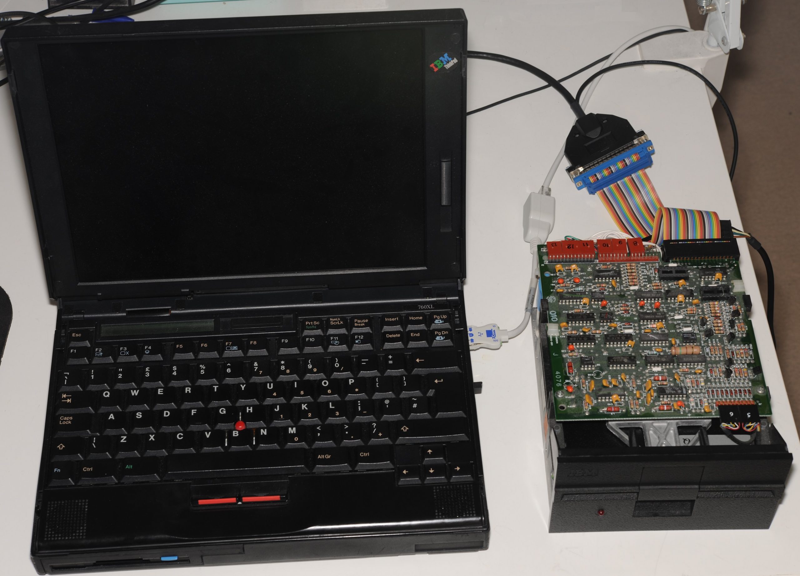
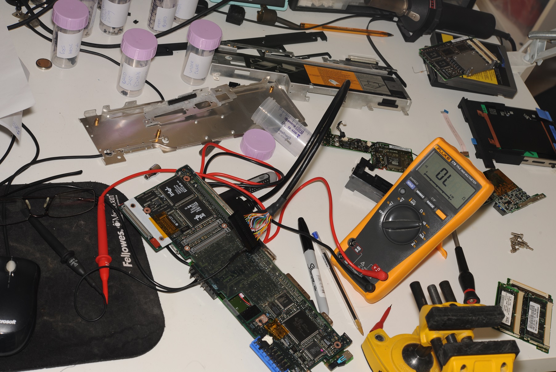
Day 1: I completely dismantle the laptop. Inside I discover that it has a half a dozen PCBs connected together with ribbons and board-to-board connectors. It’s a nightmare. I found the floppy controller, but it’s not accessible when it’s all assembled, so I can’t just beep it out. I started to beep out the rear connector to some of the intermediate connectors but it’s a sucky, time consuming exercise.
I eventually discover that only two pins (RDATA, WDATA) are directly connected to the floppy controller, the rest are buffered separately from the internal drive, and the buffers are under the I/O PCB, between it and the CPU PCB which is really difficult to get at. I give up. While I’m at it, I can also get the +5V and GND pins easy enough. I re-assemble the laptop and ponder my next move.
Day 1 ends, I know more than I did at the outset, but unfortunately there’s still a lot of pins to work out.
Day 2: I discover that signals from the floppy controller to the internal floppy are observable on the rear connector, but signals going the other way, aren’t, because of the internal buffering. Doing some accesses to the internal floppy with a scope attached I can get a few more pins – STEP, WGATE, SIDE, DIR.
Day 2 ends, and there’s still more to go.
Day 3: I’ve now written a small DOS program which allows me to read and write the registers in the floppy controller. With this I am able to get TRACK0, WP, DSKCHG and DRVSEL/MOTEN.

Day 3 ends, I’ve got one signal left: INDEX. All of the inputs have 20K pull-ups on them, so I have to assume that the remaining unidentified pin with a 20K pull-up is INDEX.
Day 4: I’ve got all of the floppy signals now, I’ve got still got quite a few unknown and it bugs me that I wasn’t able to confirm the INDEX signal. It seems to work with it disconnected, so do I really have the INDEX signal? FFS. Pull it open again…
While I was at it, I got another two signals, DRATE0/DRATE1. Not sure what those are for. I haven’t used them.
The Thinkpad external floppy pinout
(On models which use a 26-pin mini-D ribbon connector) – I can proudly announce:

Note: Newer models (i.e. 770) use a slightly smaller D-type connector. This may not be the pinout for those.
Difficulty #2 – Cable

There’s nothing special about the connector – it’s a Mini-D Ribbon connector (MDR). I found some cheap ones on eBay labelled “1Pcs SCSI 26 Pin MDR Male CN Solder Plug” which were exactly what I wanted – solder termination, also including a decent shell.
After much pondering as to what would go on the other end – I’ve settled on a standard DC-37 (yes, DC. Not DB) external floppy connector as used on IBM machines in the 1980s.
As one can imagine this cable is quite a bit of work to assemble.
Difficulty #3 – The BIOS doesn’t support 5¼” drives
This is hardly surprising as Laptop BIOSes typically don’t have features not corresponding to official accessories, and realistically, who on earth would have wanted to do that at the time.
I was fearful that there’s be a serial EEPROM in the floppy drive containing product identification data, that I’d be stuffed without the contents of, but that doesn’t turn out to be the case. I attached a generic 3½ floppy drive to my newly made cable – it works. An additional bonus, I can also boot from an external 3½ drive of my choice, should I ever feel the need to.
Back to the matter at hand. My Thinkpad 760 runs Windows NT 4.0, which has its own floppy disk driver, not using the BIOS at all, except, it does interrogate it to find out what kind of drive is attached, which is where we have a problem.
The type of drive is retrieved by NT very early on via an INT 13h call to the BIOS, that data gets stashed in a holding area, finally retrieved by floppy.sys a bit later on when it starts up.
Hacking the response to the INT 13h call would be pretty difficult, so instead I’ve gone down the path of hacking floppy.sys, whose source code is in the NT4 DDK.
After days of screwing around with my floppy NT driver hack not quite working I change approach – and go hack NTDETECT.COM – an obscure 16 bit executable which is used during the NT boot process to probe the BIOS for hardware information, including attached floppy drives. Using the NT leaked sources, this turned out to be absurdly easy, however re-compiling it most certainly was not.
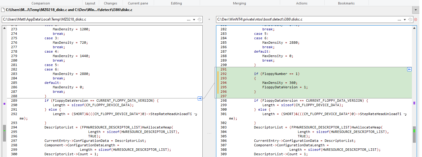
Eager hackers have gone to the trouble of re-creating Microsoft’s build environment from the early 1990s. Even with all of the know-how in the public domain this is still an awful lot of work, so I put together a custom build environment for it instead. My new NTDETECT is quite a bit bigger (35K) than the original (26K) for some reason, but it works.
Read data troubles
I noticed fairly quickly that I was having quite a lot of read errors, so I got out the scope to have a look at RDATA

It seems that the 20K pull-ups inside the laptop aren’t sufficient for my cable rig. I had to add 1K pull-ups on the RDATA and INDEX signals to get things looking a bit cleaner.
Would you believe it…
The day after I complete this, after nearly two years of watching eBay – a first generation Thinkpad external floppy appears on eBay UK. I nab it for £6.50.
Let’s crack it open and see what’s inside.
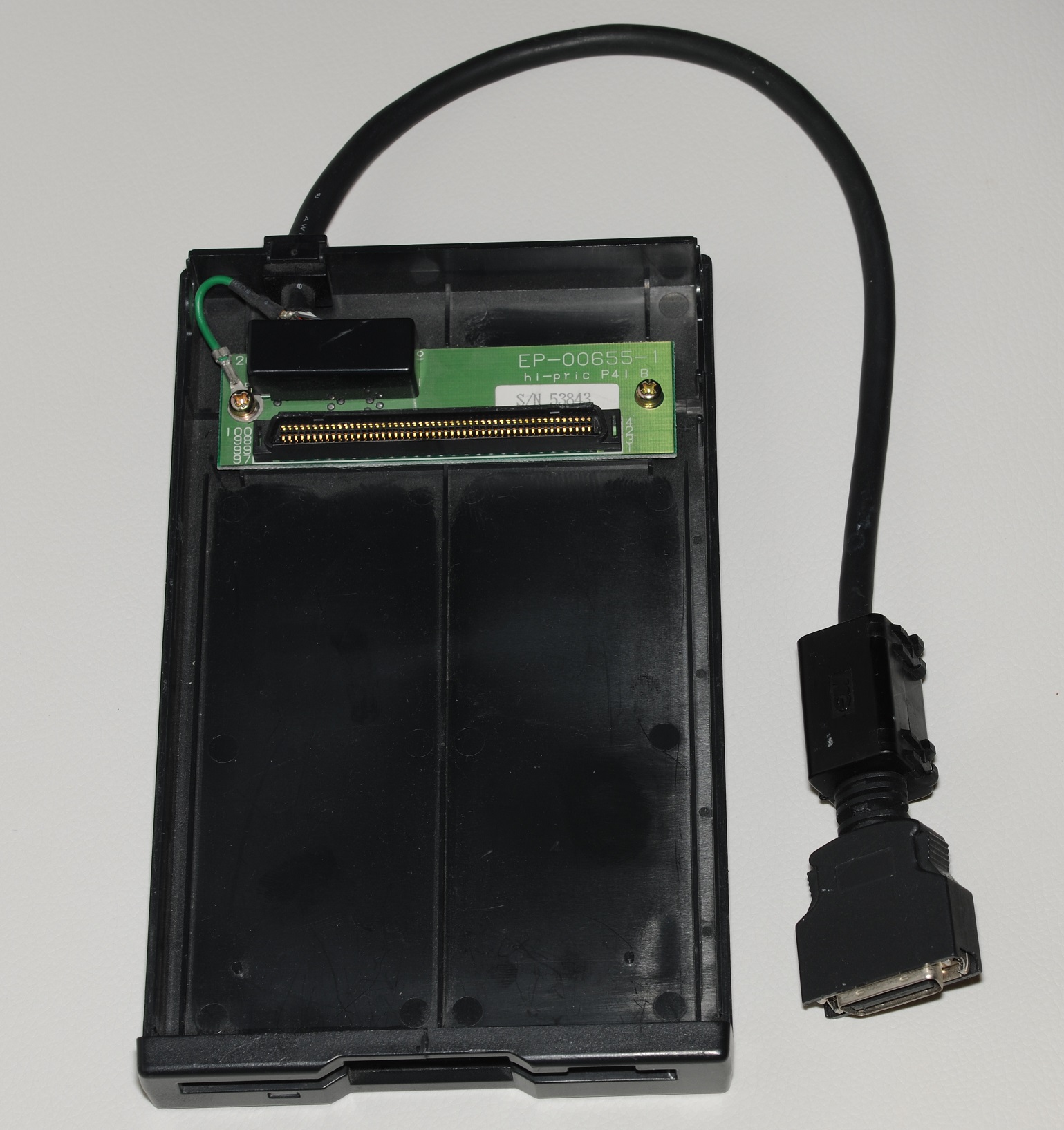
It turns out the external floppy is just a caddy which can have the internal floppy drive inserted into it. Busting it open actually tells us nothing about the pinout of the rear connector, because we don’t know the pinout of that large 100 pin connector inside it.
To get the pinout I had to detach the Mylar FPC which runs between that connector and the physical drive, which has a 26 pin connector on it, which we do know the pinout for, because it’s a TEAC FD-05HF-8830 for which the datasheet is available. Finally, I can beep this thing out properly.
What did I learn from it?
The only new information I got is that the HDSEL signal is actually present on the external floppy interface. It’s a bit of an odd one. It’s an output from the drive which is LOW when a 720K disk is inserted, and HIGH when a 1.44MB disk is inserted.
What’s the point of it? Not sure. Generally floppy drivers do this detection in software, first trying the highest format for that type of drive, if that fails, step it down, try again, and again and so-on.
Because it’s not connected to the FDC (it’s connected to an undocumented IBM ASIC) nothing much would be able to make use of it anyway. It’s probably used by the BIOS to make format detection a bit quicker, but the BIOS is also able to do format detection in software, so, really not needed.
Other than that, a few mystery pins were found to go to NC pins on the drive. I think it’s for some kind of drive identification mechanism, which isn’t used on the drive I have.
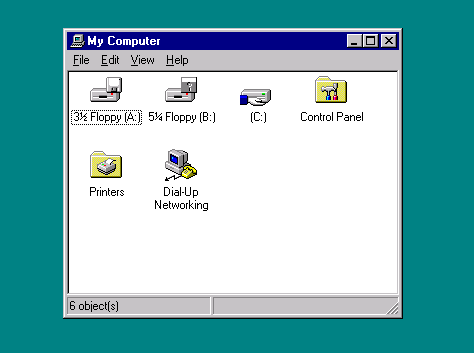
A general note about using 5¼” drives on modern computers
You may be sitting here thinking: “I don’t have one of those ports on my laptop. Why couldn’t he have shown how to do this with an interface I have on my computer”. I hear you.
I would also dearly love to to just plug this drive into my Windows 10 laptop, have that 5¼” icon show up in My Computer and use the drive like a modern USB floppy, heck, even running one from a parallel port would be amazing.
Unfortunately, when the writers of the USB Floppy Specification decided only to include 720K and 1.4MB formats on 3½” drives in the standard, they made this extremely difficult. Because of this, a whole new software stack would have to be written, for which ever OS you want to use (it’d be easier on Linux – being open source you could modify what’s there). For Windows this would take even an experienced driver developer several months. Ditto for any other interface.
Maybe, just maybe, the source code for a newer Microsoft operating system (with the USB floppy driver) will one day find its way into the public domain. We can then modify it to support 5¼” drives – 90% easier than re-writing it from scratch. Until this day comes, hacks like the one this article describes are about as good as it’s going to get.
Failing that, there are other possible solutions. It is theoretically possible to attach a Super I/O (with floppy controller) to the LPC bus (assuming your mainboard has a header for it – many do). A bit of new hardware would have to built, as well as a bit of software hackery, but this would still be fairly easy compared to building a whole new soltion.
Posted in Vintage PC
No wonder you needed pull-ups, your drive is missing the terminator!
(The DIP package in the socket near the connector, see https://upload.wikimedia.org/wikipedia/commons/d/d6/IBM_Floppy_Drive_With_DOS.jpg)
Good spotting. I’ll take a look at that next time I get that old beast out!
A note about the 360K vs 1.2M format. Two things – RPM and data rate! That is the reason for the density select line going to the custom ASIC chip. Sets the data rate down for 720K (assuming the 3.5″ drive.) Reason is thus: 720K 3.5″ was still 80 tracks, BUT only NINE sectors per track WITH A DATA RATE of only 250KHz instead of the 500KHz used for 1.44M. The 1.2M 5.25″ drive spun at only 360RPM, while the 3.5″ drive spins at 300 RPM. That is the fundamental difference. By using a slower spindle RPM, the 3.5″ drive can stuff 9 sectors (512K) per track at 250KHz for the 720K format (80 tracks x 2 sides), and at the 500KHz data rate, 18 sectors per track (720K doubled = 1.44M). In order to get that 360K DSDD floppy drive to work, you need to force that DENSITY SELECT line low, which enables the 250KHz data rate. Ironically, the 360K DSDD drive used the same RPM – 300! However, only 40 tracks, NOT 80. So in order to get it working correctly, set the density to low, and use a format utility that allows you to select the number of sectors and tracks. NFORMAT under DOS will do that. And yes, the BIOS sets the number of tracks to 80 for a 3.5″ drive regardless of density. OMNIFLOP can also do that in Windows. LINUX doesn’t use the BIOS parameters, so with the FDUTILS package, you can again specify tracks, sectors and also data rate.
Your information could be useful for connecting a floppy emulator to the thinkpads. Thank you.
Hi, great review! Could you please also post the pinout from the 26-pin mini-D ribbon connector to the DB-25PIN connector ? So we can solder the same cable fast ?
At the moment you posted only the Pinout on ThinkPad side of the conector, but its unclear, which pins on 26pin Mini-D goes on which pin on DB-25.
Thanks
The connector in the photo is not a DB-25. It’s a DC-37. You have something with one of those on it? I’d like to know more!
Sorry, for such a long pause between replies.
I have 3 Computer with this floppy connector:
IBM ThinkPad 760XD
Apple PowerBook 2400c
Hyundai Super-LT6
While Apple PowerBook 2400c has totaly different wiring of the connector, the Hyundai “could: be compatible. Need to check it.
Could you maybe create 1 more cable? I would of course pay all the parts, shipping and your working time.
Thanks
Wow, nicely done, i’m trying to pull something similar with Datavue Spark laptop which does have an EXT FDD connector (da 15pin) and a lack of documentation. Can you share your fdcreg program or it’s source, maybe on github? I would really appreciate this! Thank you!