Is it really this difficult to get modern LED Christmas lights to default to “on” ?
EDIT: Most of the information on this page is superseded by this project.
Wrapped your house in LED Christmas lights, put it all on timer (or some other automated control mechanism), only to discover that the default setting for your LED Christmas lights is an annoying comically blinky pattern, certain to invoke questions about your standing in society?
That happens to be just the position I recently found myself in and apparently this is a common annoyance of 2-wire LED Christmas lights, presently the most common type. In this YouTube video Big Clive reveals that some power supplies have an unpopulated option for a memory chip, which preserves the selected pattern after power-off.
Unfortunately you probably didn’t get the option to have that installed in your lights, and also like me have discovered that even if such an option exists inside the power supply, opening it non destructively is near impossible. Some of these units have an 8 hours on, 16 hours off timer which sort of half solves this problem, but not in my, and many others opinion.

Rather than messing around modifying an existing LED Christmas light power supply, I was keen to see how an entirely new LED Christmas light supply could be built, in particular one which defaults to “all lights on, no blinking or patterns of any sort”.
The challenge
I went ahead and attached the output of my supplied unit to a scope to see what is outputted in the “steady on” setting, the one you most likely are to want, the one which you have to push the button 7 sodding times to get.

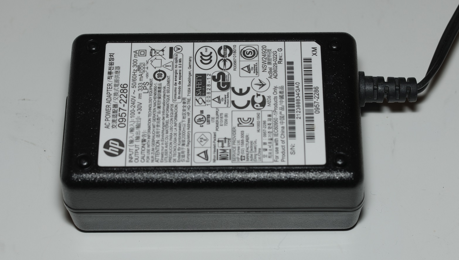
From the above we can see that it outputs a 72 volt peak-to-peak (36 VAC) square wave alternating current voltage, at around 500 hertz. In theory this is simple to generate, just find a 36 volt DC source and swap the polarity 500 times a second, but in practice it is annoyingly difficult. The voltage will vary depending on the manufacturer, but will always be printed on the side of the unit.
Finding a source of 36 volts (or whatever may be required)
Inkjet printers are typically supplied with power bricks with voltages around this range. A quick search on eBay reveals a number of units with voltage outputs ranging from 28 to 36 volts. You may be lucky and find one that outputs the correct voltage for your lights. If not, purchase one with a higher output, and trim the voltage as needed by adding a string of, for example 1N4001 rectifier diodes.
Converting DC to AC

The most straight forward way to do this is with an H Bridge. In this example I’ll be using the L298, a primitive, inefficient device, from the ark. As much as I’m not a fan of the L298, it does do the job with as fewer components as possible, and can handle the higher voltage requirement and is available cheaply fitted to a ready-to-use PCBs.

The next thing we need is two alternating 500hz square signals, 180° out of phase with respect to each other. The most straight forward way I could think to do this is with a 555 timer and a 74HC74 D type flip flop. This results in two perfect square wave signals with exactly 50% duty cycle (preferable to getting into long, detailed, opinionated discussions about how to do this without a flip-flop). Yes, it could be done with an 8 pin microcontroller but then the software has to be built, chip programmed etc. What a hassle.


Something a bit more proper
At the time I built the above Christmas was fast approaching and I really just needed to throw something together quick.
I have since designed a PCB which combines all of this together in a more elegant design, with a convenient 12V DC input:

Read more about it here.
Posted in Circuit snippets
Thank you for your great work! I have three questions…. 1. Do you know the load that the lights consume? 2. Is the PCB ready? Is it open source and available? 3. In your document, you say that the power comes from the two separate power supplies in series. However, in your schematic that you mention as a work in progress, you have the power supply there. You didn’t mention that in your document. Did you reverse engineer the power supplies? Are they still external to this PCB? Have you managed to incorporate the power supply to the PCB, thus removing the need to rely on the external supplies?
Ah yes. Good to know I’m not the only one getting into the festive spirit like 3 months early. The project has been published here: https://www.mattmillman.com/projects/simple-2-wire-led-christmas-light-controller/
> Do you know the load that the lights consume?
I do not. LED Christmas light strings are anywhere from 200 to 2000 lights in lengths so depend what you have and how they are wired!
Hello. I admire your innovative approach and the later stages showcasing the printed circuit design. Dealing with multifunction lights can indeed be a total pain. I have a simple battery-powered set myself and was hoping if it’s possible to obtain a schematic for this uncomplicated setup. I can’t make out all the details from the photo. I’m eager to try it out myself. Thank you.