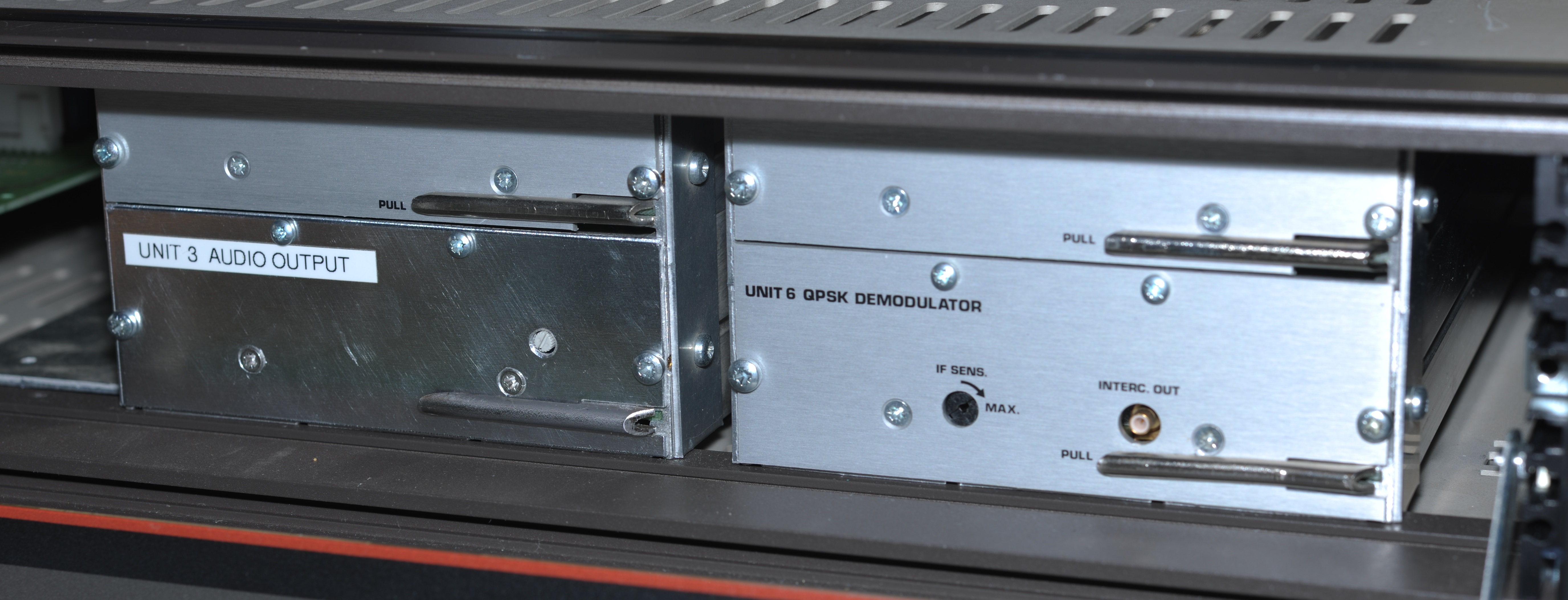
Back when I was looking at these one of the units I purchased was incomplete. The seller had warned and it was priced accordingly. I had planned to break it up and scrap it for parts, and I did. But I had a change of heart, put it back together and set about seeing if I could re-make it. It’s a unique bit of kit which deserves a place in my interesting things corner.
Predictably it would be the audio output assembly with the valuable TDA1541A DAC that was missing. It came from Silicon Valley with an asset sticker of the swashbuckling chip maker Broadcom attached.
With the dot-matrix LED displays also missing (those and the DAC are the bits I would steal) and our thief certainly located in the USA, it seems likely it was pinched by a fellow hobbyist for some kind of CD playback related project as its original purpose was irrelevant in that particular country.
I can’t say with any sincerity that I actually need it, but I think re-making one of these would be an interesting and satisfying project. I haven’t done anything analogue audio related for 20 years now and building a through-hole PCB is always a treat.

Fortunately I do have a complete sample to study. From a cursory glance it looks feasible to re-build. Most of the components are either still in production or easily obtainable. With it being an ultimate benchmark of the standard, it’s not good enough to end up with something “so-so” or “yeah, it’ll do”. To be worth bothering with it has to be an exact recreation of the original. This is not going to be easy as we’ll see.
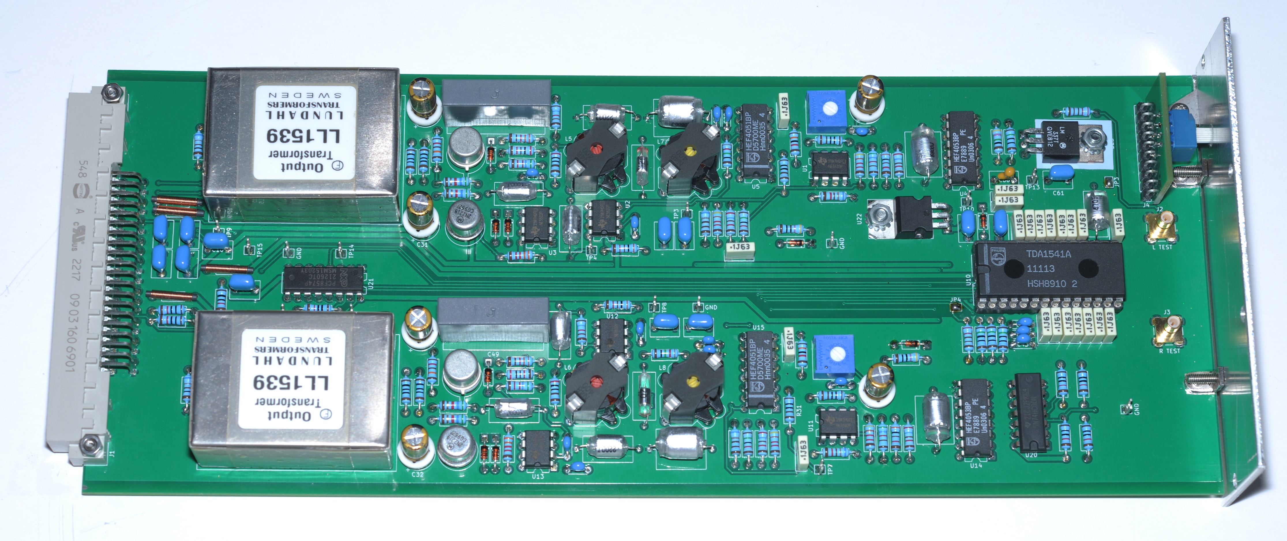
And just like that it’s done. Tracing out and re-doing the artwork for the original PCB was straight forward, as was obtaining most of the components. The original is made almost entirely from Philips components.
That is not a realistic proposition these days, thus this one is not. There’s not a lot else to say about the design/construction. There are however a few other areas worth talking about…
Anti-aliasing filters
The original board was designed with a 5th order elliptic low-pass filter (by appearance – mathematically it may be a different design) using a combination of Philips KS series Polystyrene capacitors and bespoke inductors. The inductors were made in-house by Philips using their own RM6 cores. Similar parts are also seen on the BBC’s NICAM-676 solution (also using the TDA1541A). This business has since passed to ferroxcube. Trying to unravel the thoughts of the original engineers, specifically why these were chosen is perhaps a challenge for another time. For now I just want to copy what’s in hand because this is not a trivial subject. I couldn’t find any stockists of the original parts, so instead chose comparable parts from TDK. But which parts?
These ferrites turn out to be a massive product family. Aside from the many different sizes of core, each comes in a multitude of material types, each with differing properties. Some don’t have a core air-gap, others have an air-gap, and there’s many different gap sizes. Some cores are adjustable, others aren’t. Within each style there’s different types of bobbin too. There’s also an adjuster screw with a piece of ferrite material. There’s a bunch of different types of those as well.
Frustratingly there is no cross-reference between the Philips and TDK parts. This was a real headache and required hours and hours of research, studying detailed specifications trying to work out what the equivalent TDK parts were.
Once I established this I purchased some sample cores and bobbins. Before I attempted any winding I first de-soldered the original inductors and began to characterise them. No point in unwinding them. For one I don’t want to destroy them, and there’s no point in doing this anyway because the TDK cores will not be 100% identical. Instead I need to establish a proper spec. I made L, Q and DCR measurements at a range of different audible frequencies using a high end LCR meter, with the adjuster removed, then with the adjuster at the each end of its travel. Detailed measurements of the state they were found in were also made.

Now I know a lot about what I have in hand. Time to try and make some more. First difficulty – what wire size is used? It measured at 0.2mm using my callipers, so I tried this. After winding one core I found I had achieved target inductance with far less wire but DCR was double and Q was too low. Too small. I then tried 0.3mm. I couldn’t achieve target inductance and fit on the wire on the bobbin. Too big. I then tried 0.25mm. Bullseye. DCR almost spot on at target inductance, Q also measured the same. I broke two bobbins and wasted a crapload of wire trying to get them right but got there eventually.
Even having worked out how to wind equivalent inductors I’m still not done because the Xicon Polystyrene capacitors I bought for the job are 5% tolerance. The inductors will need to be tuned to compensate.
Tuning the filters
Prepared for difficulty I developed an application which allows me to sweep the filters using a benchtop DMM and function generator. There is a separate post for this.

Let’s take a look at some actual sweeps, comparing the original to the new one I’ve built.

Above is a comparison of the anti-alias filters with de-emphasis switched off. Absolutely bang on. They’re only active from about 15 KHz onwards, so I started this sweep at 10 KHz.

Above is the normal operating mode with de-emphasis switched on. Also very good but there’s a tiny bit of error under 300 Hz. It’s so minimal that it’s still within the channel-to-channel error of the original assembly. This is due to component tolerances and unfortunately the design doesn’t allow for any tuning of the de-emphasis filter. I can fix this, but won’t bore you with the details of that particular process 😉
Balanced output circuit

I could probably write pages about the design of this thing, but in particular I really like the final stage amplifier. Let’s take a quick look.
There are several interesting features. The first is the string of three diodes between the bases of the output drivers. A fairly common feature of this type of amplifier, they ensure that there’s no crossover distortion by keeping each half nominally biased at 1.5 times VBE. The drawback is that they’re always burning off a little bit of power through R61 and R62, but this is a low powered circuit. Who cares. It’s a price worth paying.
The next is that it incorporates an offset servo through R51, R57 and C48. This is a carefully balanced circuit which captures and corrects the DC offset of the amplifier to ensure that neither Q1 or Q2 are trying to pull on the transformer at idle, but also minimising direct feedback from them.
The main feedback path is through an auxiliary winding on the transformer. This corrects any nonlinearities of the transformer.
The result is a perfectly equalised, zero distortion, isolated output. That my friend, is how a balanced output is done.
The best part: Audio transformers
Such an elegant output stage must of course be matched by its transformer. These were made by Swedish audio transformer designer Lars Lundahl. Back when Philips purchased the originals Lundahl was just a small business run by him and his wife. To my amazement the business survives, now having passed to their son. Still making exactly the same parts. Exactly.

I probably could have found some as scrap but such a purchase would be almost criminal considering they were able to supply two brand new LL1539 output transformers, to the exact specification of the 35 year old originals. I doubt I’ll ever solder down a component of such legacy ever again.
Schematic
- Can be downloaded here
Further developments
About a year after I completed this project by extraordinary luck I managed to obtain the original Philips schematics for the Audio Output unit. You can view them here.
Conclusion
The decadence of recreating part of a receiver for an obsolete broadcast standard is not lost on me, especially with the TDA1541A and LL1539 being pricey parts. Nonetheless it was fun to build. There is also an opportunity to rework those filters for a future CD player related project.
Posted in NICAM, Repair / modification