NICAM Digital Audio first went on air in 1986 and is one of the, if not the first digital broadcast received by households in much of Europe and Asia/Oceania (excl. Australia). It is well remembered by both AV enthusiasts and audiophiles for providing near CD quality audio alongside analogue television broadcasts. For my teenage self, watching the music video charts with the stereo attached to a NICAM receiver was always a highlight of the week.

It was originally developed by the BBC for FM radio backhaul and likely still used for that to-date. There are many pages around the internet discussing its theory and history. Myself, I’m keen to get my hands on some of the kit, look at it and see if I can make it work.
For the most part, NICAM broadcasts ceased around a decade ago. With this technology obsolete, the original broadcast equipment is now scrap, obtainable within a curiosity budget. Finally people like myself can actually get a look at it.
NICAM vs Zweikanalton vs MTS
Before I start taking things apart, it’s worth covering this briefly. Zweikanalton was another stereo TV sound standard which competed with NICAM in the PAL and SECAM world. Its biggest adopters were Germany, Australia and the Netherlands. They are functionally similar however Zweikanalton is entirely analogue. It had the advantage that receiving hardware was little more than an FM stereo radio, and was easy and inexpensive to manufacture. Transmitting equipment was also backwards compatible with earlier FM mono receivers.
NICAM on the other hand required a second disparate transmission path and a complicated and expensive receiver arrangement not included in older or more affordable receiving equipment, for which the traditional FM mono carrier had to continue to be broadcast. This meant that many consumers missed out on stereo sound due to budget constraint, ignorance or indifference.
For example, TV equipment intended for the Australian market (Zweikanalton) was commonly found in New Zealand (a NICAM country) labelled “HiFi Stereo”, but only delivering poor quality mono sound because the in-built demodulator was only able to receive the legacy FM mono carrier. This frustration was likely shared by European consumers from NICAM countries neighbouring Germany and Netherlands as economic forces shunted cheaper Zweikanalton equipment over borders.
MTS Is another analogue stereo system like Zweikanalton used exclusively with NTSC and PAL-M (effectively NTSC) broadcasts.
One of the biggest drawbacks of Zweikanalton was that the audio had to somehow be transported to the site of transmission as an analogue signal, recalling the very problems the BBC were trying to solve with NICAM.
NICAM Broadcast Equipment
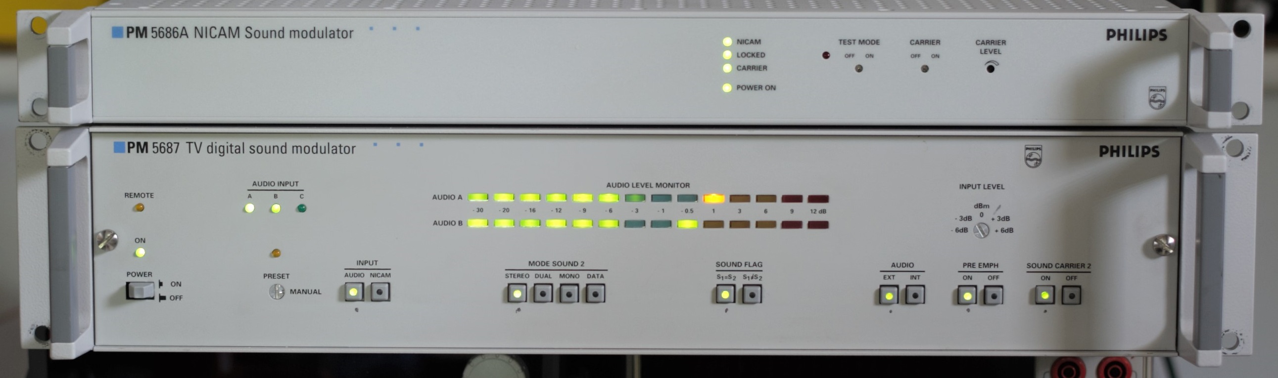
On this page I’ll be looking at three pieces of equipment from Philips introduced at the IBC-88 trade show. I have various samples of this equipment dated from 1987 to 1992:
- PM5687: Studio component: Digitises analogue audio and encodes it to NICAM. Optionally it can also modulate a ready-to-broadcast carrier if fitted with Unit 6 (details below)
- PM5686A: Transmitter component: Modulates pre-encoded input from PM5685 or PM5687
- PM5688: Test NICAM receiver (separate post)
See also: List of known NICAM-728 Encoders.
There are several related pieces of equipment I do not have:
- PM5685: Cut down version of PM5687. Digitises and encodes only (Unit 6 not fitted)
- PM5689: “Affordable” replacement for the PM5688 launched in 1995. No other details available
- PM5684: “NICAM transceiver” – Reference found in this magazine. No details available. Purpose unknown
- PM5680: Accompanying vision / analogue audio modulator

A detailed look at the PM5687
The PM5687 speaks the design language of another era, consisting almost entirely of off-the-shelf through-hole components. Everything is done the hard way. It does however pack everything into a single 2RU enclosure. The components within date it around 1992 – for most adopting countries the beginning of the NICAM era
Later on, even more refined solutions appeared like the Factum Electronik NC200A which uses surface mount components, custom ICs and offers two channels in a single 1RU enclosure.
I do not have the manual for this item. I couldn’t find it online either. I suspect it only existed on paper, and it wasn’t included in the sale. Thus a lot of what I’ve stated here is from experimentation or guesswork.
Internal components

Looking in the top with the cover removed we can immediately see some classic money-is-no-object engineering. The unit has a very complicated structure of machined/extruded/cast aluminum parts held together with more than a hundred screws, weighing in at over 10 kilograms.

Undoing the two screws on the front panel I discover that it folds down, revealing the delightful mechanical construction allowing the internal modules to be removed by simply removing the screws and pulling the eject lever.
There are three modules each connected to the backplane with DIN41612 60 Regular / 4 Coax connectors and an empty slot for a mystery fourth.
Unit 3 – Audio Input

This module’s job is to take the analogue audio signals from the rear inputs and digitise them, ready for the codec which we’ll be looking at shortly. We’re immediately confronted by an enormous filter network on a mezzanine PCB. I haven’t studied it in detail (yet) but I think it is a Chebyshev or Butterworth filter using a swag of adjustable inductors and ultra-stable polystyrene capacitors. It would have to have been manually tuned on the production line.
It’s job is to deliver every precious hertz of audio spectrum to the ADC appropriately equalised, blocking anything it cannot digitise (i.e. >16 KHz).
I attached my headphones to the two test points at the output of this board to listen to what is delivered to the ADC. It seems to prefer higher frequencies, attenuating those at the lower end, even with the pre-emphasis switched off. This effect is somehow cancelled out by the time the audio reaches the listening end.

Removing the filter mezzanine we can now see all of the analogue goodies underneath. There are few components which aren’t made by Philips. There are some here made by Signetics however this was owned by Philips at the time this was made. Even the capacitors are all Philips. I never knew they made these too.

Here they are annotated.


Unit 5 – Baseband Coder
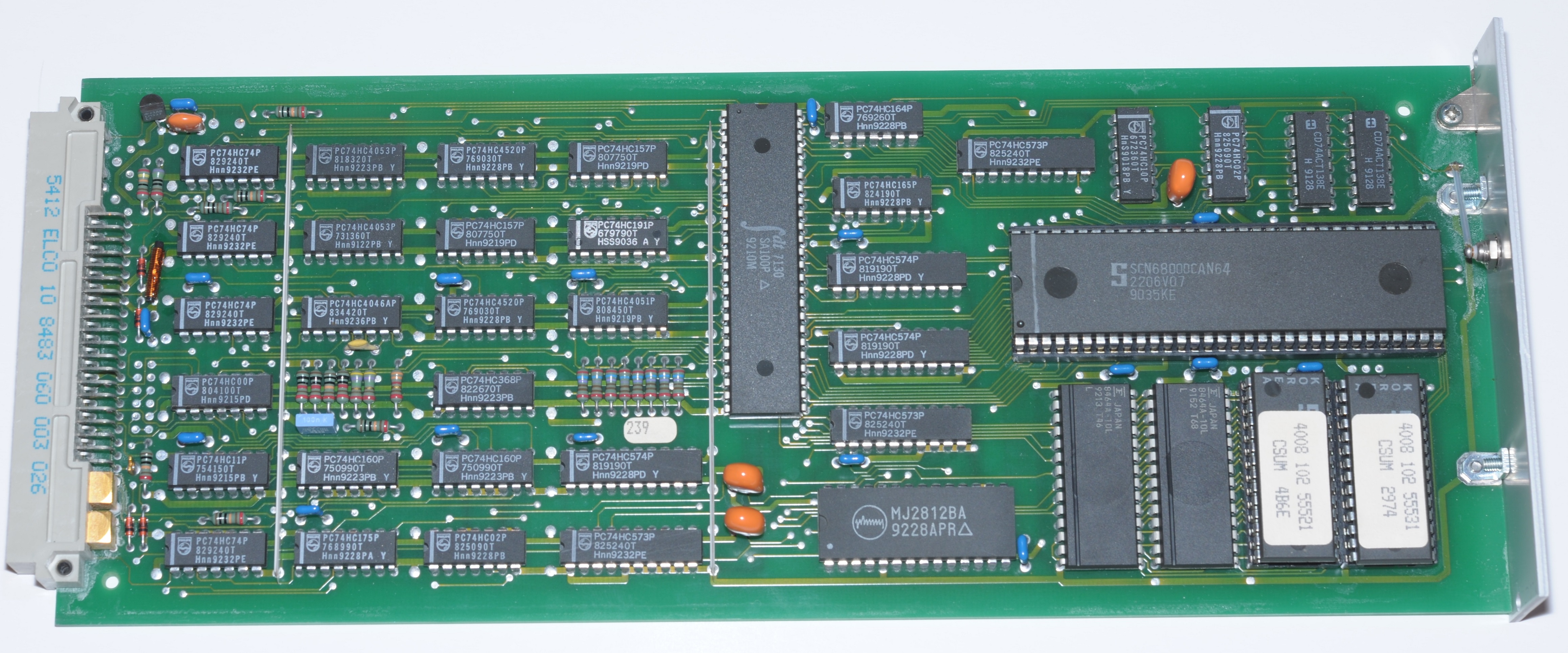
This board was a surprise for me. It’s effectively the NICAM codec (“coder” in the language of the day), implemented in software. Philips drafted in what at the time would have been a grunty 68K processor for the task. Gaining a detailed understanding of how this module works would be quite an undertaking. However it works, it has to do things darned quickly else there would be issues with lipsync.

Unit 6 – QPSK Modulator (Optional)

This board’s job is to turn the digital bitstream generated by the codec into an RF signal (a modulated DQPSK carrier) that can be broadcast. It is unlikely to be required at a studio location where this unit would normally be situated, thus, Philips also offered a version of this equipment without this module fitted with the model number PM5685.
It is this board which decides whether or not a carrier for the CCIR System B/G/D/K (PAL/SECAM) or System I (PAL I) standard is produced.
We can get a sense if how some of it operates from page 24 of the NICAM specification.

However this board features plenty of magic not detailed in the NICAM specification. The two oscillators are phase locked to the 200KHz clock from the master oscillator. This allows the broadcaster the lock the carrier frequency to their provided 10 MHz reference. 200 KHz is chosen because both 5.85 MHz (B/G/D/K) and 6.552 MHz (I) can be divided down to it.
Another interesting feature is that it is a direct-conversion transmitter with the 33.05 MHz 1st IF as its output. Not the 5.85 MHz intercarrier as suggested by the NICAM spec. The intercarrier is generated by an additional hetrodyne stage powered by a mysterious (or not?) mixer IC – OQ0702P (looks like a TCA240 to me) and the 38.9 MHz oscillator. Philips probably did this to minimise phase noise on the 1st IF output, which is the most likely to be used.
Frequency reference (master oscillator)

The PM5687 did not disappoint here either. Packing a 10 MHz TCXO from Philips @ 5 ppm. Not enough to satisfy meteorology buffs but more than good enough for broadcast.
There’s a couple of fractional dividers to provide the 5.842 MHz clock (for the NICAM encoder) as well as the 200 KHz clock which appears to head to the DQPSK modulator. Performing divide is the ‘HC4059 counter and the trusty ‘HC4046 PLL for multiply. Notice that the passives normally required for the ‘HC4046’s VCO are missing. Philips apparently weren’t satisfied with the in-built VCO so disabled it and rolled their own based on an exotic CA3130 CMOS op-amp. From a quick bit of research this was a technique to build an ultra-stable VCO back in the old days.
The internal 10 MHz oscillator can be disabled, making the 10 MHz output at the rear an input, if an even more precise 10 MHz reference is available.

Front panel

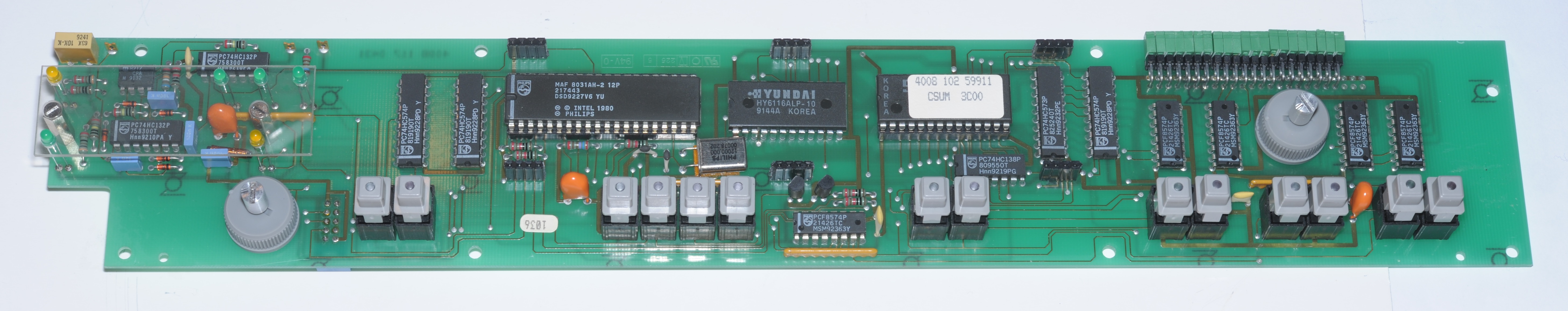
Removing the VU meter we can see the whole unit is driven by a Philips branded MCS-51 microcontroller bolstered with external SRAM and EPROM clocked at a very generous 12 MHz. Given that it’s got to drive the VU meter and deal with incoming SCPI commands this was probably needed.

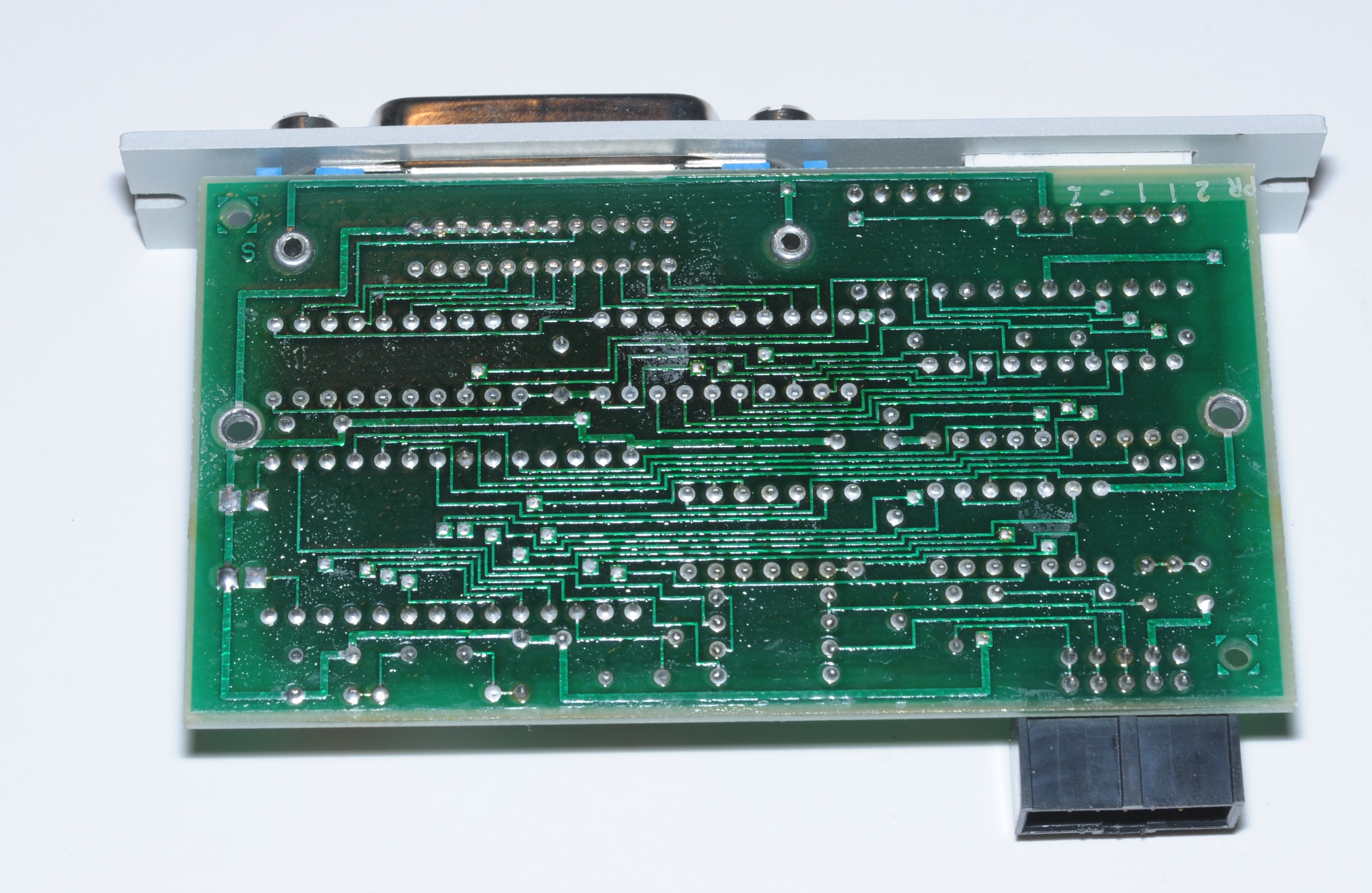
GPIB Interface

And it’s a Philips branded MCS-48 on here. This one appears to be Philips version of the Intel 8021. A mask ROM version with 28 pins. There’s no hope of dumping the code from this one but it appears that isn’t necessary. The MCS-48 on the front panel appears to be the one interpreting the SCPI commands as I can see them all in the ROM dump.
Front panel

Controls on the front panel are as follows:
INPUT
Switches between analogue inputs and pre-encoded digital inputs (NICAM IN).
MODE SOUND 2
Toggles input between stereo / mono / dual (bilingual), changing the stereo/mono/dual flag used by receivers in the process. Data setting purpose unknown.
“Sound 2” refers to NICAM. “Sound 1” is the FM mono audio not handled by this unit.
SOUND FLAG
This toggles the “The reserve sound switching flag” detailed in section 4.2.2.3 of the NICAM specification. This tells receiver that the FM mono carrier is carrying different audio entirely to the NICAM carrier. An obscure, rarely activated scenario which was envisaged as an option to carry three languages (two NICAM + one FM) however I cannot find any evidence this was ever done.
AUDIO
Switches between analogue audio input or test tone generated in software by codec.
PRE EMPH
SOUND CARRIER 2
Enables/disables internal DQPSK modulator. Allows the broadcaster to disable NICAM and force receivers to fall back to FM mono audio.
Rear panel

AUDIO A/B IN
Left and right audio inputs in stereo single language mode. Language A and Language B in “Dual” mode.
AUDIO C IN
This input allows the mono (audio out) connector be sourced separately from the A+B channels. It does so when the sound flag is set to S1≠S2. Hypothetically it’d allow three different audio tracks (two NICAM + one FM) as stated earlier.
AUDIO OUT
For connection to the legacy FM mono modulator. It is either the A+B channels combined or the C channel only when the the “sound flag” is set to S1≠S2.
In some cases the FM mono modulator wouldn’t be in the same location as this unit. It would be interesting to know how this was dealt with.
IF OUT (Intermediate Frequency)
Broadband NICAM output modulated onto a 33.05 MHz carrier. This is for a 38.9 MHz IF system (where the vision carrier is at 38.9 MHz) intended to be directly combined with vision/audio IF carriers before up-conversion (or after, depending on the scale of the transmitter). Spectrum is inverted compared to intercarrier output.
IF IN
Connected to the same passive combiner the IF output connector is attached to. This could, for example, be connected to the IF output of the analogue audio/vision modulator.
NICAM OUT/CLOCK OUT
Baseband output from the codec. Used where the carrier is modulated in a different location to where the audio signal is digitised / encoded.
NICAM IN/CLOCK IN
Baseband input to the internal modulator. Allows the unit to be used as a modulator only in the case where the audio signal is digitised / encoded elsewhere. The internal modulator is switched between the internal codec and the connector on the front panel.
INTER C. OUT (intercarrier)
Outputs the original 5.85 MHz NICAM carrier (for B/G models like this one) for scenarios where video/FM mono/NICAM are all modulated/upconverted together. For the PAL-I model the intercarrier frequency is 6.552 MHz.
REF IN/OUT
Internal 10 MHz reference output, or in the case where it is configured as an input, it would likely be connected to an atomic clock.
IEEE 488
GPIB remote control port. For example, the studio may have some sequencing system that needs to change the configuration of this unit when a bilingual broadcast is on air.
Testing the PM5687
The first thing I checked when powering on was the IF output:

As expected, there is a carrier output 700 KHz wide, at 33.05 MHz

The output demodulates perfectly.

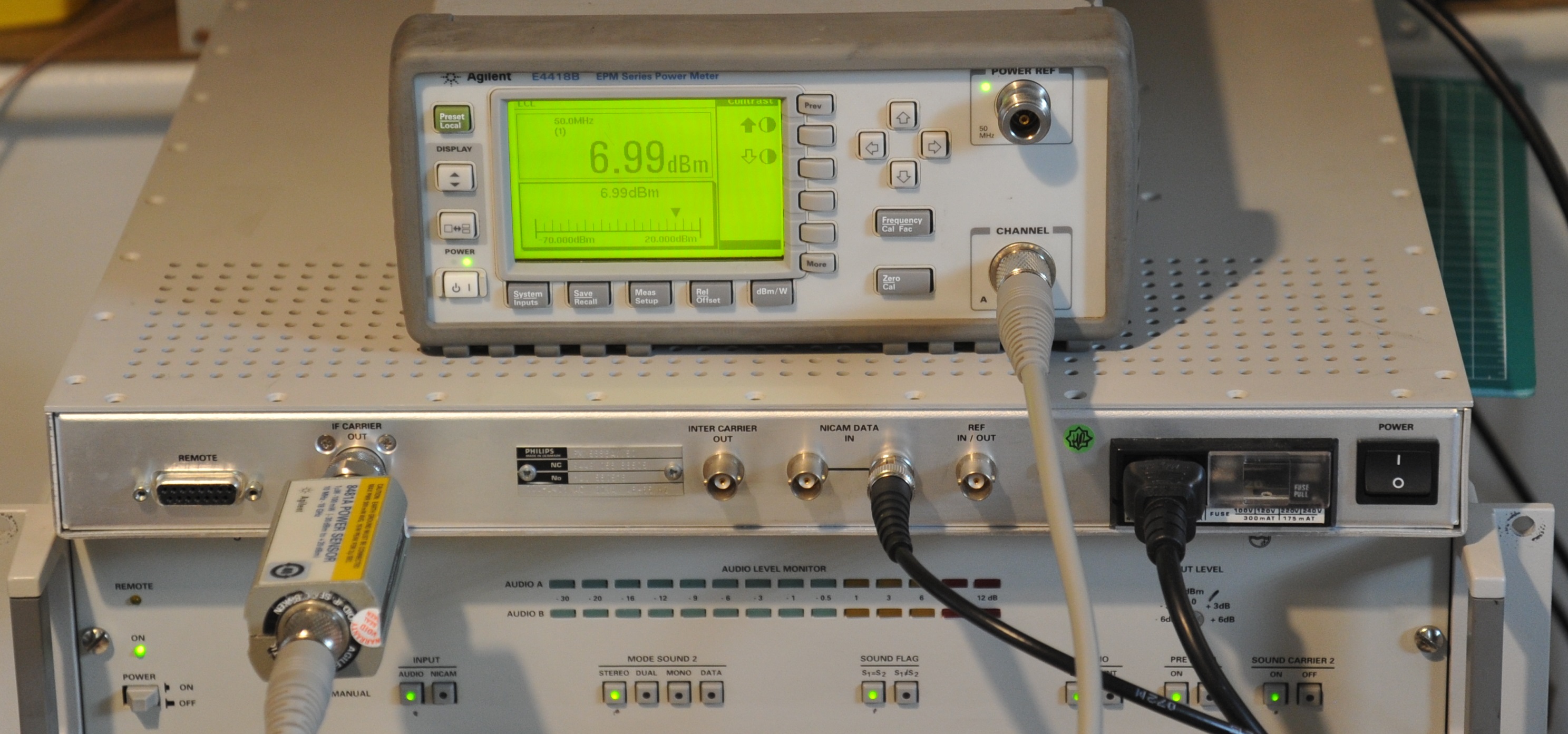
There was an entertaining discovery testing the IF power, It’s -20 dBm. Exactly.
That’s about all the testing I can perform with the instrumentation I have to hand.
A detailed look at the PM5686A
This piece of equipment would have normally been situated at a transmission site hanging off an E1 leased line with a PM5687 or PM5685 on the other end back at the studios. It is an entirely digital device which does not handle the audio in analogue form.
After removing about three and a half thousand screws I finally got the top cover off:

The mechanical construction did not disappoint here either. To remove each module was simply a case of removing the one screw in the centre of the PCB, sliding that PCB forward a half an inch then effortlessly folding it out. They even attached a pair of machined knobs to each card to assist with the disconnection / connection / raising / lowering of the cards.
The internals were almost as expected. It’s centered around the same DQPSK modulator module found in the PM5687. There are some minor differences – the main being that this one is setup for PAL-I.
Oscillator / Clock recovery module

To the left we have an array of 74 series logic which performs clock recovery from the incoming NICAM signal as the unit does not accept a separate clock input. This gives the customer maximum flexibility as to what carries the digital NICAM signal as only a single connection is required.
Interestingly the oscillator is 2 ppm. Better than the 5 ppm seen on the PM5687. This makes sense as the stability of the broadcasted carrier matters more than the codec clock.
DQPSK modulator

Very similar to the one found in the PM5687. The differences I can spot:
- The baseband output logic is missing, because this unit does not have those connections
- Oscillators are crystal based instead of RC. I’d guess the benefit is that they stabilise quicker
- Nominal clock of carrier circuit is 32.348 MHz (set by crystal)
- Jumpers on carrier clock circuit are set differently to phase-lock the frequency to 32.348 MHz
- Test mode switch not fitted + various mechanical differences

IF Amplifier

The presence of this further bolsters the case of this being from transmission site use. It’s got a big scary looking RF power transistor on the underside.
Measuring the IF
The IF frequency of this unit is 32.348 MHz. 702 KHz lower than the PAL B/G model as we would expect. Bear in mind that the IF output is spectrally inverted hence the lower frequency.

I was interested to find out what kind of output power we’re seeing from that IF given there’s an amplifier in this unit, and the large the size of that transistor on it. I dug out my power attenuator, cranked the dial on the front to the max and prepared to be vaporised:
It turns out to be a little lower than I was expecting. This one must have had its output turned down.
Up next
In part 2 I’ll be looking at receiving equipment, and of course getting it working.
Posted in Broadcast tech, NICAM, Vintage audio
Slightly off-topic but a bit more background.
HiFi Stereo VHS VCR’s were available in NZ long before TV3 started broadcasting in 1989 in NICAM. They did allow playback of Stereo VHS tapes and like you I connected my National VCR to a stereo for the better sound. Mine recorded the broadcast tv sound in mono but also allowed recording of stereo sound on the HiFi tracks. Some tv shows were simulcast on FM radio (especially music videos – “Radio with Pictures” on Magic 91 FM in Auckland and “Live Aid”) and you could connect a FM tuner to the VCR and record in stereo.
Hi Matthew
I have read your article with high interest. This is mainly that I also have 2 x PM 5687 units with the intention of trying to get them working. As you say an impressive bit of kit. Information is indeed thin on the ground. I also have some professional RF Generators which can accept a Nicam or IF input, so these may work with this Philips unit. I can guess that these units were not cheap back in the day! What a tragedy that these wonderfully engineered units are now on the scrap heap of Technology with digital broadcasting now the norm.
Wow. That brings the known number of survivors to 5. What type? PM5687G (System B/G) or PM5687I (System I) ?
If they’re System I units you can probably just do what I did on this page:
https://www.mattmillman.com/remembering-nicam-part-2-recreating-a-pal-i-signal-and-receiving-it-with-something-fancy/
Of course if you want to combine them with a broadcast vision modulator that is quite another matter. I can also help out with this if needed.
They were not cheap. USD 9000 each back in the day.
Could you dump the ROM’s from the Baseband Coder card?
https://github.com/inaxeon/PTV_Preservation/tree/main/PM5687