As high powered as you want

For a number of years now I’ve had a couple of high powered switching power supply units made by Power-One. They’re typically found in I.T. equipment and provide a single output rail of either 12 V or 48 V with a very high current rating.
In the case of the 12 V model – the output voltage can be changed in software from 1 V to 12 V (12.45 V is the max). The 48 V model does not allow configuration of the output voltage frustratingly.
While they’re very flexible and provide a tremendous amount of current – they’re not so straight forward to hook up to other things.

In this series there are 3 main models:
- FNP600 – Available as 12 V (51 A) or 48 V (12.6 A)
- FNP850 – Available as 12V (69.5 / 73 A) only
- FNP1000 – Available as 48 V (21 A) only

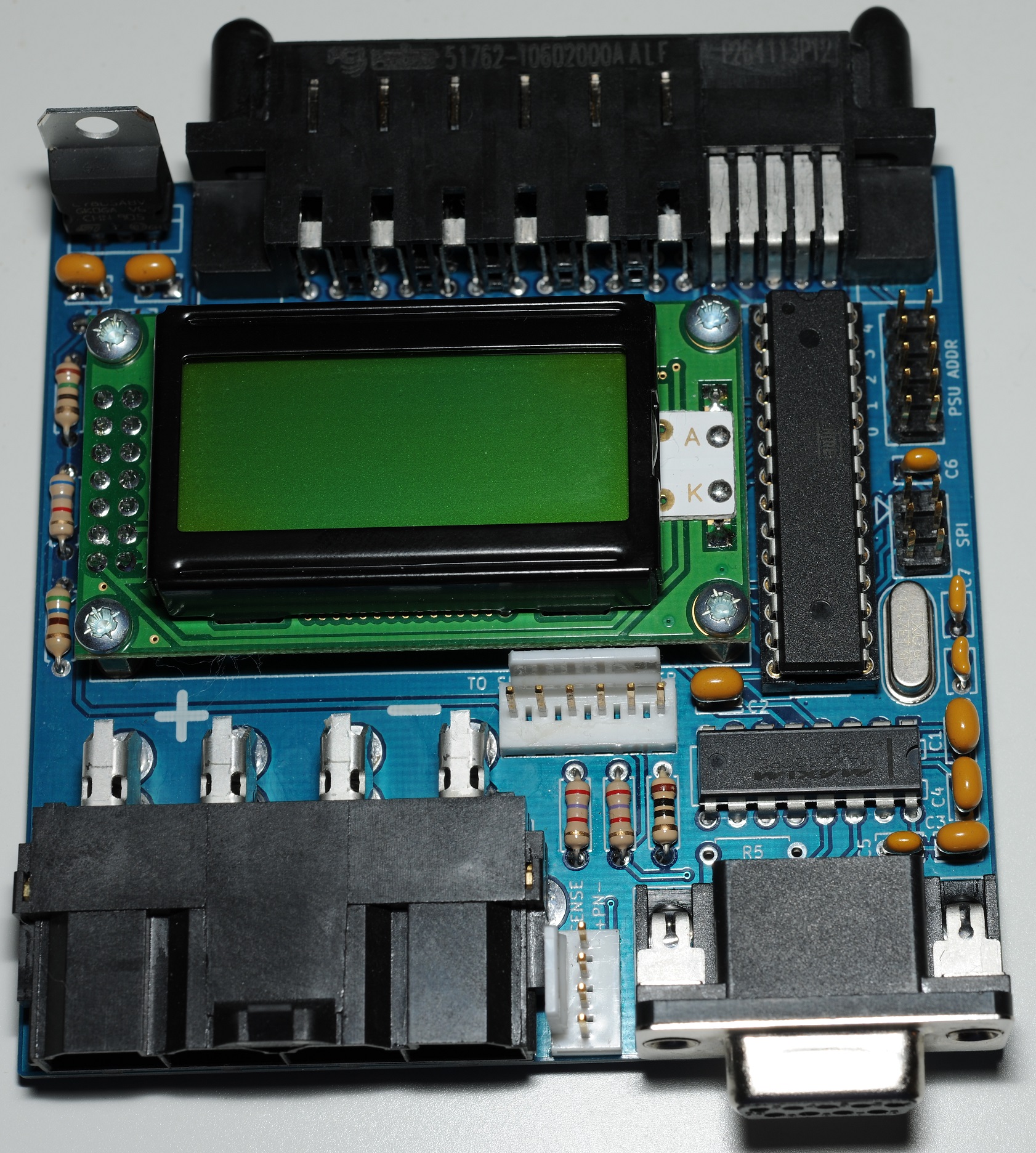
Some time ago I built the above adapter board, which has a small PIC microcontroller allowing me to change the voltage, and also adapt that obscure FCI PwrBlade connector to something easier to deal with – in this case Molex Minit-Fit Sr.
Recently I was prowling eBay looking for the FNP850 model (which I didn’t originally possess) – and, I find that there’s craploads of them for sale, very cheaply. I picked up a couple of FNP850’s for £15 each free shipping – quite a deal when these originally sold for about 30 times that!
The model which is most plentiful is the FNP850-S151G (12 V 69.5 A) which appears to be a customised version of the original FNP850-12RG (12 V 73 A). The only differences the S151G has from the original 12RG model is the S151G has some extra grounding contacts built into the chassis, it’s been de-rated a little and does not have variable fan speed – it’s at 100% all the time annoyingly.
My discovery that these things are so cheap and plentiful has become the basis of this project – essentially I’ve cleaned up my original implementation for the PIC microcontroller, ported it to AVR – because nobody likes expensive compilers, and released it on Github. I’ve also designed a proper PCB for it.
Design
The board is an all through-hole design the same width of the power supply units. I’ve added an 8×2 LCD which shows the current either configured or measured output voltage, and the output current (the sum between all units when multiple are connected).
The board can be built either as a master or as a slave.
The output connector on my boards is a 4 position Mini-Fit Sr connector however if this is not suitable there is also a couple of 5mm holes under that connector which could be used to bolt cables directly onto the PCB.
Master
The master board has everything fitted – LCD, microcontroller, RS-232 port.


Slave
A slave board has only the connector which mates with the PSU, the jumpers for setting the I2C address, the remote sense header and the header for connection to the master, which has all the needed signals.
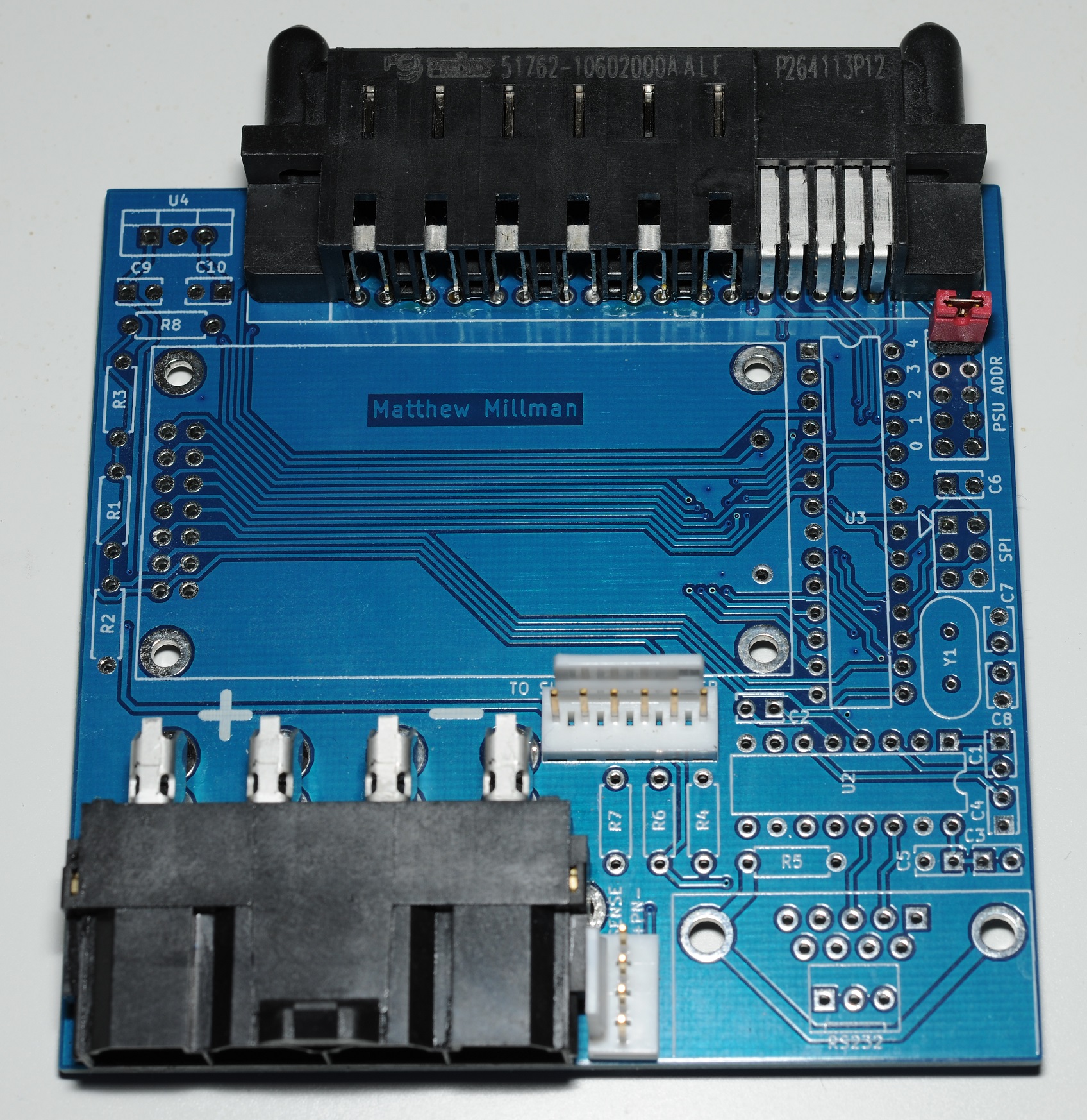
A slave board could also be used for a “Dumb” output board, or for connection to a different microcontroller.
Using multiple units in parallel
These power supplies have an active current sharing mechanism which is one of the signals on the connector between the master and slave boards. The characteristics of this mechanism is generally what limits the number of supplies which can be used in parallel.
If you need more than 70A – you can connect quite a few of these in parallel. I don’t know what the exact limit is but Power-One make a chassis which can take up to 5 of these, so you’ll get at least that many.
With 5 in parallel we’d have 350 A (4.25 kW) to play with – not something you’re going to be plugging into a regular socket outlet!
The software I’ve written will automatically detect and operate multiple units. Provided everything’s hooked up properly.
Testing units at full power in parallel
For my test I’ll be running two units in parallel – giving us about 140 A @ 12V. Consuming this much current at such a low voltage is actually not so straight forward.
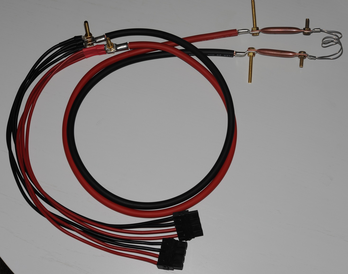
My test load is simple: Some big cables with some large Nichrome wire on the end of it.
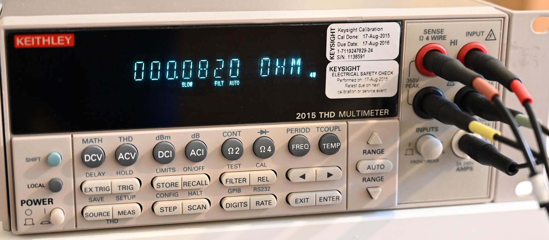
The test load measures about 0.082 ohm which will get us just a little over the full 140 A load @ 12V I cut down the Nichrome wire till I got this measurement.
When we also consider that this’ll change under load, and that we’ve got more resistance on the feed cables it’s quite tough to get it spot on at build time.

And of course that Nichrome wire has to be submerged under plenty of water otherwise it’d disappear in a flash – potentially causing me personal injury.
In this test I took the time to connect the sense wires otherwise we wouldn’t get to full power due to loss in the cable. I was able to boil that basin of water in about 10 minutes.

And there we have it. Full power – two supplies in parallel! In the end I had to tweak the output voltage until I got roughly 140 A into my test load.
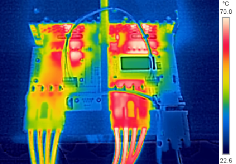
Thermal camera images of the test setup at full power reveal things getting uncomfortably hot. If you are going to be running this rig at full power long term pay particular attention to the thermals. In my case I found I had to extend some cowling from the power supplies over these PCBs to leverage the fans in the power supply – avoiding a meltdown.
Command line interface
The RS-232 port will present a command line interface at 9600 baud which is usable at all times during operation.
Here is the output of the help command:
cmd>?

Commands:

measure|ctrl+e
Show the measured output voltage/current readings

outvoltage|o [1.00 to 12.45]
Sets the output voltage of the attached power supplies

on|<pgup>
Enable the main power output

off|<pgdn>
Disable the main power output

startmode [0 or 1]
Set to '1' if the power output is to be ON after AC power on

expectedpsus [0 to 8]
Do not power up unless N number of power supplies are detected
Set to 0 to disable this check

measuredvoltage [0 or 1]
Set to '1' to show the measured voltage on the LCD instead of
configured voltage

show
Show the persisted configuration

default
Load the default configuration

reset
Reset this board

cmd>
Limitations
There are of course a few limitations with this setup, which you should consider before attempting to build it!
- Output voltage is not continuously variable. The output has to be disabled and re-enabled for a new configured voltage to take effect. The software I’ve written does this automatically – this means you’ll get a 500ms “off” period whenever changing voltage
- You cannot connect the supplies in series. The main output voltage is referenced to the chassis/earth.
- The 48V FNP1000 model does not have a configurable output voltage
- In countries with a 110V electricity supply – these supplies are de-rated down to 740 W.
- These supplies having 40mm fans, as you can imagine, are quite noisy
Building it yourself
Source code for the AVR
Can be found on GitHub here.
Schematic
Can be downloaded here.
Gerbers
Can be downloaded here.
BOM
Can be downloaded here.
Very interested in this. What a great way to get a nice high output supply on a budget. Hope you finish publishing details on this.
It should be completed in the next month or two!
Did you ever get back around to this? With all this time I’d love to do this project!
Sorry about that. Gerbers are uploaded now. With eBay awash with ex-bitcoin mining power supplies didn’t think there’d much interest in this project and forgot about it!
Matt,
I’d bought the PSU before and wanted to use it. I finally finished this project this week. Had to learn to flash an atmega328 along the way and get my linux environment all setup for this, but it worked, and it was a fun little project. Thanx!
OLIVER
Part number for the FCI PwrBlade connector?
Thanks
51762-10602000AALF
Hi,
Do you have specification of the I2C bus for these PSU’s ? Commands list etc ?
Thanks
Google “fnp850 i2c programming”
Hi Matt,
Awesome project! I’ve made 2, and they are working great! I would like to add an ESP32 to connect them over WIFI (and maybe a small TFT display), but I cannot find what load the auxiliary output can support. Do you know how much amps it can handle?
Thanks!
Datasheet is available:
https://datasheet.octopart.com/FNP1000-48G-Bel-Power-Solutions-datasheet-9790073.pdf
500ma
Hi Matt, first of all I wanted to tell you that you are crazy haha. I wanted to ask you, a while ago I acquired a PWR-3900-AC 3925/3945 power supply from a Cisco Router and to use it as a 5, 12 and 52V power supply since it has a large number of output Amperes to use in the laboratory. The thing is that I can’t find any diagram nor a way to turn it on by making a jumper on the connection terminals. Do you have any idea how this can be done? Thank you very much and greetings from Argentina.