This little LCD Controller is the first I ever purchased back in 2011 and I’ve bought a few more over the years for various projects, suffice to say that it’s been my workhorse.
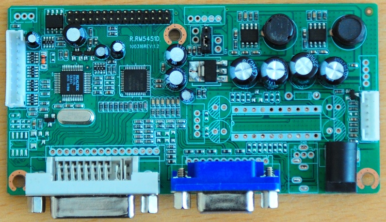
It features a common Realtek 8051 CPU (RTD2120L) and a less common scaler, the RTD2525 (or RTD2545 for the higher resolution R.RM5451).
It also comes in a variant with no DVI input (R.RM3xxxx) as well as a TV variant (R.RM6xxxx) which I’ve never touched.

The majority of Realtek based LCD monitors ever made had the RTD2120S CPU coupled with the RTD2553V or similar scaler, so the R.RMxxxx family are a bit unusual, but from a hardware perspective, there’s not much between them, it just runs different firmware.
Anyway, back to the subject at hand… In terms of its firmware, its OSD looks and feels a little more budget than what you’d normally find on a big name LCD Monitor, but it’s still the best available for hobbyists in my opinion. I don’t know for absolute certain, but from my poking around in the code running on these boards, it appears to be the handy work of this company.

The board comes in four versions, aside from the obvious variations (Audio and no audio) and here’s a breakdown of the less obvious differences:
| Model | DVI input | Max pixel clock | Onboard +3.3V |
| R.RM3251 | No | 82MHz | Linear |
| R.RM3451 | No | 105MHz | Switching |
| R.RM5251 | Yes | 82MHz | Linear |
| R.RM5451 | Yes | 105Mhz | Switching |
Max pixel clock
This effectively limits the refresh rate and resolution. Sellers often state this as “Max resolution” but this is the isn’t the right way to look at it.
Let’s take a common panel (LP141WP4) with a native resolution of 1440×900, and we’re using a refresh reate of 60Hz. It’s specified to have a blanking periods of 160 pixels horizontally and 26 pixels vertically, so we end up with 1600×926 pixels that have to be transmitted for each frame, which is 1,481,600 pixels
Now just multiply that by the refresh rate:
1,481,600 * 60(Hz) = 88,896,000 (88.8MHz)
So by that calculation, LP171WP4 would be slightly over the limit of what the R.RMx251 boards could handle, by my observations they can handle a little over, but I wouldn’t bank on it.
If we went to 70Hz on that same panel, now we end up with:
1,481,600 * 70(Hz)= 103,712,000 (103MHz)
At this point it would fall over, and the higher rated board would be required.
Most of this relates to the VGA input as the ratings are for the Analogue to Digital converter. With DVI input, higher pixels clocks are easier attained for both boards.
Onboard +3.3V
The boards with the higher rated pixel clock have switching regulators to support larger panels. +5V is switching on both boards.
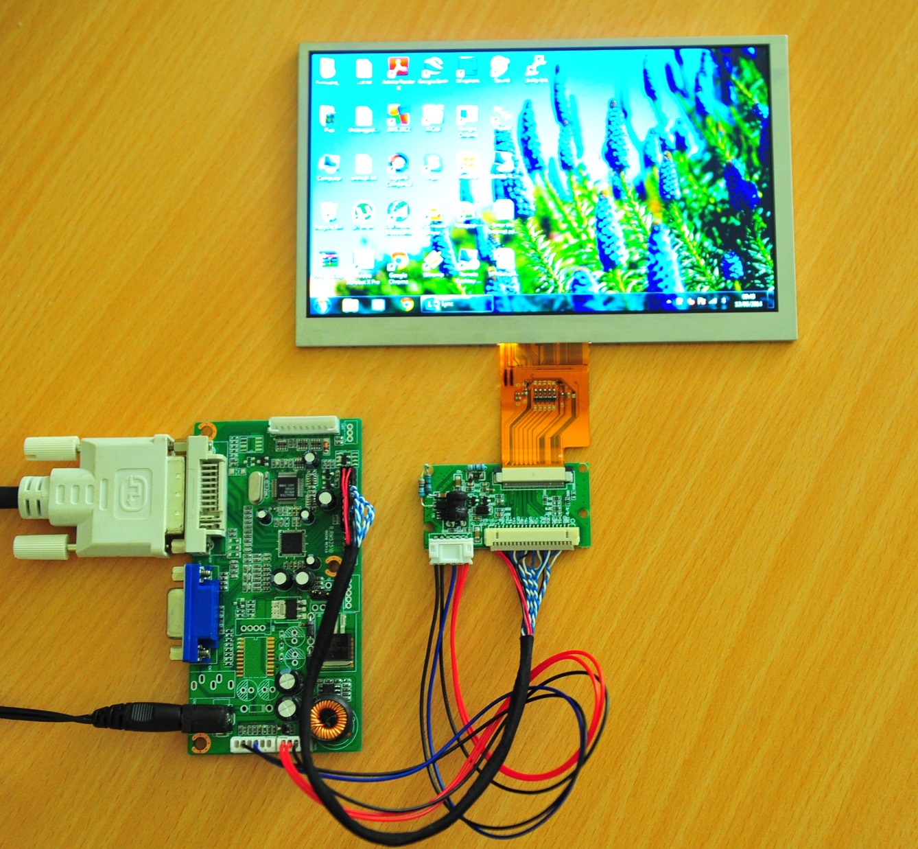
I was told by NJYTouch that AT070TNA2-V1 wasn’t supported by this board, which officially may be true, but, eh, I’ve written a program to edit its firmware, so I can use it with any panel I please 😉
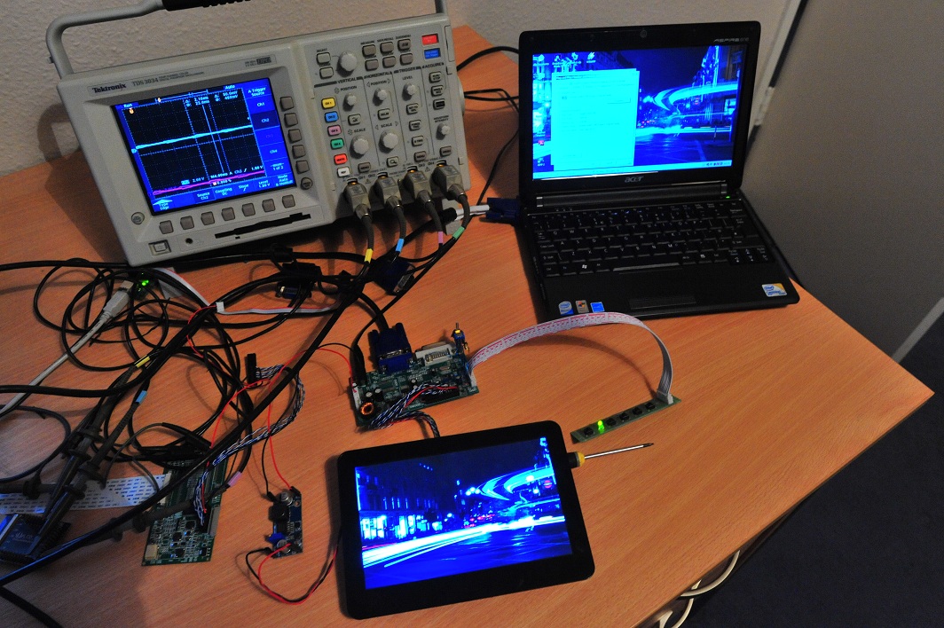
Conclusion: Having done quite a few LCD projects with different boards, this is the one to go for. It’s a good package for serious users (who buy the programmer), It’s fully supported by my ROVATools suite, and for those buying the pre-programmed board, it’s got about the best chance of working as expected 😉
Hi Matt, I recently bought one of these boards, albeit a slightly different version: 5251b (rev. 1.9), with the intention of paring it with a Raspberry Pi. I’m trying to see if I can pull the 5v for the Pi off this board instead of needing two power sources. Judging by the jumper, it’s already outputting 5v. Do you know what the current is at 5v, and/or is this even feasible? I have a limited electronics background so I’m trying to be careful not to fry anything. Any input is appreciated… Thanks.
The answer is yes and no. The Raspberry Pi3 will boot up and run, but with the power warning, and the Raspberry Pi2 will work but without peripherals plugged in and you get the power warning periodically depending on the load.
Hi Matt,
Great work, I’ve got two 2009 iMacs which I do not believe it will make cut for the next Apple OS upgrade. Plus I recently discovered the 12v rail supplying the HDD failing, however works great with SSD and now running debian. The other iMac, I want to gut and possibly run with a raspberry pi since the 2009 body has lots of room and perfectly good shell as it would be a shame to discard. My question is, I’ve been looking around but unsure, do you think the R.RM5451 would work for the LM215WF3-SLA1?
Feel free to email
Mark
Hi. I already posted on on the other blog . I need to use this LDC with a windows 10 computer: NL8048AC21-01F.
Can I use this board and your tools with this lcd?
Hello.
I have an old R.RM5451 board and his parallel board programmer.
I have a Samsung 17″ panel ref : LTN170U1-L01.
How can I program the R.RM5451 board ?
I don’t have any “firmware” (or gff file or ?) for this screen.
Anyone can help me please ?
Many thnaks