Introduction
As of Release 2.0 this mechanism now offers the best balance of simplicity and low cost.
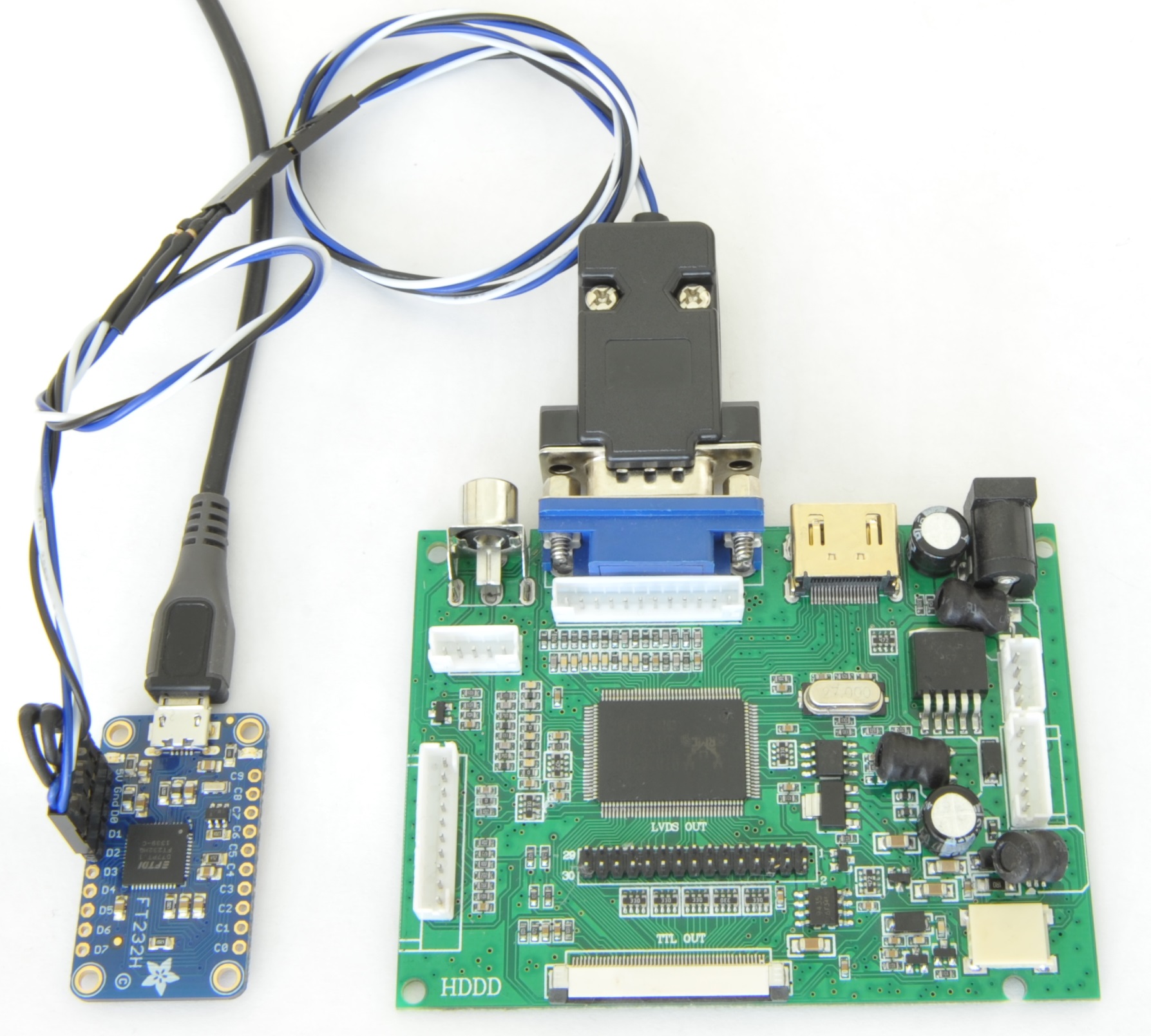
This page describes how to get a commonly available FT232H based board, the Adafruit FT232H Breakout working with ROVATool.
The first step is to wire it up. You’ll need:
- Adafruit FT232H Breakout (or anything else like it)
- 2x 1k resistors
- 2x 100 ohm resistors (optional)
- DE15 Male connector
- Some hookup wire
- Optional 0.1″ headers and housings
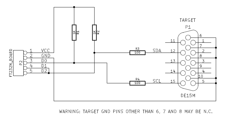
The connection process is described on Adafruit’s website here for completeness sake, here’s a schematic:
Warning to purchasers of non-Adafruit FT232H boards
I have received several emails from people who have unsuccessfully tried to get this working with non-Adafruit branded FT232H boards. Just because it has the same chip, and is wired the same as I have demonstrated here, does not guarantee that it’s going to work.
These boards have an EEPROM containing some data which is used by the FTDI driver to determine the capabilities and configuration of the board. ROVATool does not have any control over this, it simply requests the first available I2C channel. The exact implementation of that is determined entirely by your board and its own EEPROM. Some boards to not advertise I2C capability at all, while others do, but using different pinning to the Adafruit board.
With the proper know-how – in the worst case using FTDI SDK to reprogram it, you will be able to fix it, however this is not a simple task, and I do not offer assistance in these cases.
Drivers
I personally recommend the V2.10 D2XX driver from FTDI, which is included in the package. Others should work, but, for example, with V2.12 – I have seen one minor issue.
Other FTDI chips
Although I’ve not personally verified them – other chips such as FT2232C, FT2232H and FT4232H should also work, provided they have the correct EEPROM configuration for I2C operation, and are wired correctly.
The MStar USB programmer (FT2232D) is also fully supported by this release.
Can be used as “USB ISP Board” ???
Hi Matt,
Thanks for sharing your great work. I read your review about the Novatek NT68667 / EasyWriter, so I am hoping that I can pick your brain.
I bought an M.NT68676.2A board from ebay, which was programmed for the wrong LCD panel and due to shipping cost I’m not all that existed to ship it back in order to get that corrected. I’m looking for a low cost solution to reprogram the board. Do you know If this can be used with the Novatek EasyWriter?
Or alternatively, I have a logic analyzer based on the Cypress CY68013A that I can modify in according to the instructions that you posted, do you know if there is a relationship between NVT EasyUSB that is listed in the supported EasyWriter ISPs to the Cypress EZUSB-FX2?
Thanks
Nurio
Dear Nurio,
Do you solved the problem?
I asked this because and I have this problem, and I need to reflash my M.NT68676.2 board.
I will build the Parallel port programmer for PCB800099 (http://tech.mattmillman.com/wp-content/files/ParallelProgrammer.pdf)
(I found the schematic here: http://tech.mattmillman.com/lcd/rovatools/)
If you solved or not solved the problem please write back.
Regards,
David,
pdavdika@hotmail.com
Hi David,
Sorry for the late response, in case it’s too late for you then hopefully someone else will find this information useful.
I tried building the VGA programmer as described on this site using an FTDI Breakout board based on the FT2232H, which is basically an FT232H with two channels. And it seemed to work to some degree as it could read the EDID off the NT68667 board using one of the tools from this site (it’s been a while since I’ve done this and I can’t remember which one), but the Novatek EasyWriter wasn’t able to recognize it as a programmer. I’ve also tried other programming applications without any success.
Eventually I broke down and bought an RT809F from eBay that works well with Novatek EasyWriter. However, it won’t be a cost-effective solution if you don’t have any other uses for it.
Regards,
Nurio
Hi Nurio,
Yesterday I builded the LPT programmer, but don’t work.
When I press the ISP ON button the “Enter ISP Fail!” error message appears.
I will try reading the EDID with my LPT port programmer and post the results.
Regards,
David,
Dear Nurio,
Can you send for me your contact details?
Thanks in advance!
David
I don’t know a great deal about Novawriter but from memory, it has a configuration dialogue which sets how your parallel port adapter is wired. Did you try adjust that first?
Thanks Matt for reply,
I ran the LPT port setup, I chose the ROWA.
I measured with oscilloscope when I press the ISP ON button on SDA, SCL are signals .
When you using the programmer which device you choiced? NVT Type I, NVT Type II, CHIMEI, LG, MYSON, ROWA, SAMSUNG, INNOLUX or user define?
Thanks in advance!
David
Have you find the hex binarie file ? can you post the link ?
is it support ft232rl?
No,
Only the FT232H is good for this.
The FT232RL is only a USB-Serial converter, but the FT232H support I2C, FIFO, FT1248 and many other buses.
hello! I’m Luca
Thanks for your beautiful work!
I have a question. Can i use an Arduino board with a script for convert USB to I2C like this? https://gist.github.com/bsmr/59fbc14d7335ccab4dab806692783dee
(i have a board PCB800099-V.9 with RTD2660. I bought this but it doesn’t work with my 8″ 800×600 pixels TTL. 🙁
Thanks a lot!
Yes it would be possible to get it working with an Arduino, but quite an undertaking to implement and harden as a solution.
I would definitely be happy to co-operate with someone who was prepared to implement something like this but I will not be doing it myself!
Goodmorning,
I would like to know if a mcp2221 by microchip is shitable for this, it is a usb to i2c and i would like to use the schematic at the top of this page.
Many thanks
Good evening and thanks for this really useful tool!
I am trying to use an FT232H to program an RTD2660. RovaTool finds the USB device (I’m running windows in a virtual machine), but when I hit “program target”, I get the following:
Error: device didn’t send ack byte during FTDIUSBInterface::Read
On the VGA socket, I have not connected pins 6 and 7 to ground, but I have checked that pins 6,7 and 8 are shorted, so my ground goes to pins 5, 8 and 10.
Any ideas? I will try on a real windows machine as soon as I can get my hands on one, but somehome I don’t think it’s the VM.
Found it. Dodgy power supply to the RTD. All works well, even on the VM.
Found it. Dodgy power supply to the RTD. All works well, even on the VM
But how ?
I have also same issue with ROVA TOOLS
humz cant get programming to work with the ftdi 232h always complains it cant switch to isp mode
I can confirm the CJMCU FT232H is working just fine with rovatool
no pullup resistors needed just connect d1 and d2 together and connect to vga pin 12
and connect d0 to pin 15 and you are good to go !!
(In summary, leave out the pullup resistors)
Strange. Definitely something different about your setup.
Hij Martijn,
Hoe did you solve your “cant switch tot isp mode” problem? I have the same problem over here…
Regards, Bart
Hello there!
I just wanted to say thankyou for your excellent resources – both your website, and your tools – for the reprogramming of the PCB800099 LCD drivers.
I bought a couple from Ebay, and only powered them up after having made enclosures to fit- the seller had provided screens of a higher resolution than I was expecting! But the drivers were improperly configured.
Thanks to your work, I have been able to find a BIN file that worked and now both are functioning perfectly.
For your record, I was using an Adafruit FTDI-H board., without the 100 ohm resistors.
Thanks again!
Matt
I just wanted to report that I had success uploading firmware to the PCB800099 using Matt’s ROVATOOLS package and the Adafruit FT232H breakout board and the exact circuit shown on this webpage. It just worked 😉
I had ordered these boards from China, but at first they didn’t work with my display until I found the appropriate firmware (display was just black). My display is a 7″ LVDS 1280×800 display (HSD070PWW1) and now it works well.
Thanks for taking the time to share this useful knowledge.
Hi. I have a similar problem. I get a black screen and no image on the LCD. Mine is 1024×600. Where did you get the firmware please?
You can download it here: http://files.banggood.com/2016/08/SKU213295.rar
Hello James,
I am also working on RTD2660 board with FT232H. Rova tools are not supported I2C then how can i program RTD with Rova tools.I am using D2XX drivers with I2C API provided by the FTDI website on ubuntu. But i d’not understand how can i use this.
I need your Help.
Thanks for sharing these amazing info here.
I can successfully program my PCB00099 board using my FT232-based breakout and ROVATool.
I’m a bit curious and I noticed something: The circuit given above is connected to RTD2660H (or RTD2662) chip through I2C (SDA and SCL pins on the VGA socket go directly to RTD’s SDA and SCL pins). But when I hit “Erase” or “Program”, ROVATool says that it detected the serial flash chip (e.g. W25Q80 from Winbond) on the PCB00099. So if I understood correctly, the hardware and ROVATool is used for burning the .bin file into the W25Q80 serial flash chip which is driven by RTD2660H. This means that RTD2660H does not have program memory, so the program execution is done by fetching every instruction from that serial flash chip. Am I correct? But I’ve no idea how it is performed. Because I think that a firmware should also be burnt into RTD266x because if not how does it know that it should execute the program from external flash?
So I’ve a question:
Suppose the RTD2660H (or RTD2662) chip on my PCB00099 is broken. If I replace it with a new chip, will it work? Do I need to flash the RTD chip (not external serial flash) as well?
ROVATool does not directly communicate with the serial flash chip. It accesses a special function of the RTD to do this.
The RTD has no internal flash or persisted state. As for your question about how execution works – a good question indeed. I have not ever seen any documentation on the RTD’s 8051 core, how exactly it loads/executes etc.
But if you really want to know, go read about Cypress EZ-USB microcontrollers. Those are also 8051’s which can boot directly from SPI flash. I suspect that in principle, the RTD is a pretty close copy.
Hi There! Thanks for the tool!
I get the following error when trying to program my PCB-800099:
Error: Unsupported memory device: 0xC2122013
Any idea?
Thanks a lot,
Andrea
hi , did you find any way ?
Try other computer with windows 7.
Hi , did you find any way for fix this error ?
“Error: Unsupported memory device: 0xC2122013”
this tools sopported RTD1960 ?!
Thanks …
Can you tell me what flash chip is fitted to this board?
“Error: Unsupported memory device: 0xC2122013”
My board has the same issue. I was able to modify the python script here on github:
https://github.com/juancgarcia/RTD-2660-Programmer-Python
Had to follow the instructions here to get the software to work:
https://learn.adafruit.com/adafruit-ft232h-breakout/windows-setup
Modified prog.py:
– Fixed all print statements syntax
– Added:
# Zetta
FlashDesc(“25D40” , 0xC22013, 512, 256, 64),
-Changed:
if jedec_id == 12722195:
As for the message about the unsupported device. Z25D40 with that signature has been supported for quite some time now. Perhaps you downloaded an old version?
Would it be possible to use the FT232R:
https://arduinotech.dk/shop/ft232rl-ftdi-usb-3-3v-5-5v-to-ttl-serial-adapter-module/
https://www.ftdichip.com/Products/ICs/FT232R.htm
Nope
can i use pl2303 usb to ttl to flash rtd2662?
“Error: Unsupported memory device: 0xEF124013. ”
Any idea on how to fix this?
Hi !
I really need some help…
Trying to program PCB800099
and I am getting – “Unsupported memory device: 0x5E126013”
error…
how do I locate the memory chip on the PCB ? I found two 8 pin chips but look like the are power related and not memory…
any help would be really appreciated !!!
Perhaps you could post a link to a detailed picture of this board?
I have the same error – Unsupported memory device: 0x5E126013
Can you tell me what you need? This is a generic 2660 board from eBay.
The only 8-pin memory chip I could see is a..
Z(logo) AS1904
25VQ4QATIC
P1U058C
Any help much appreciated as I’d like to get this working with a touch-screen and have a go at customising firmware.. keen to learn but having trouble getting going!
From the part number that looks to be a 4mbit device
Well the firmware I have didn’t work (not really a surprise, looks like I have work to do!) but it does indeed function as a 4MBit chip when added to the file.
Thank you so much for your excellent tool!
I have now managed to find the datasheet for the chip, or at least the chip it’s probably a generic clone of…
https://www.gigadevice.com/datasheet/gd25vq40c/
Additional – found another but I can’t find any info. It just has this cryptic number on the chip…
9345
18qGHS
I have problem. I have a PCB800661V.9-1HDMI and a WV320WHB-N00 Display. With my display tester with vga i have a perfect picture. But if i use my hdmi board i get a very dark picture but the picture is correct.
I don’t know which firmware i have on the board. Can someone help to fix the problem?
The background lighting is fed by its own supply.
When using ROVATool I get this error message: “Error: Timed out waiting to enter ISP mode”.
I’ve tried several programmers including FT232H, Arduino and Linux-VGA-port and theres always the same error.
I have added this to FlashDevices.xml to program a PCB800099 1024×600
W25Q40
0xEF124013
0x80000
Currently I am downloading the existing firmware before I flash it with a different one – so far it seems to be working…..
Where did you locate the firmware, I have 6 boards images reversed on everyone and I need to reprogram to flip the image back as there is no option currently on its menu. I was able to connect and read the 25Q40 and save a .bin file