
Introduction
Some time ago I needed to program an MCM68766 EPROM to upgrade the BIOS in an IBM PC 5150, and in the process discovered that hardware which can program these is rather difficult to come by.
So I set out to build my own. Knowing that the pin-out for 2708 EPROMs was quite similar to MCM68766 I thought I’d tick that off while I was at it, as this is another type that is very difficult to find hardware to program.
Why is MCM68766 difficult to program?
There is nothing algorithmically complicated about programming one of these – the main difficulty centres on the high Vpp voltage (26V). Most cheap EPROM programms have a max Vpp of 13V. That having been said, there are some cheap programmers which support the 2716 EPROM, also needing a Vpp of 26V, so quite why MCM68766 is such a difficulty, may also depend on other things, such as pin arrangements, or perhaps just limited demand for it.
Why is 2708/2704/TMS2716 difficult to program?
This type of EPROM is genuinely more difficult to deal with. It also needs the same high Vpp voltage, as well as an additional cocktail of voltages. +26V, +12V, +5V and -5V being the full list. All of these are required during programming – quite a headache for the designers of universal programmers. Models that do support it, require a special adapter which doesn’t come cheap. This adapter typically supplies the extra voltages which aren’t practical to provide through the universal socket. Like the MCM68766 – they are algorithmically simple to program, so no complicated software stuff to worry about.
Design
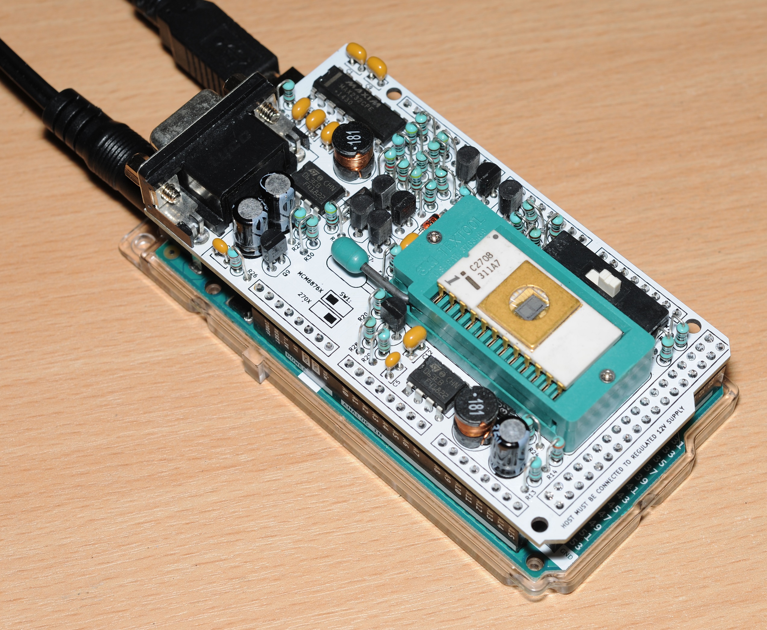
The physical design is in the form of an Arduino Mega shield. I chose this because it was large enough to accommodate all of the components, and there would be enough I/O pins without needing latches or I/O expanders.

The only supported Arduino is the Mega 2560 R3 or compatible.
When designing it I was aware that I was likely the only person that’d want something that did both, so have allowed for it to be constructed as a dual 270x/TMS2716/MCM6876x programmer, or 270x/TMS2716 only / MCM6876x only.
When built in its dual type form, selection between devices is made by a 4PDT switch, which software can query before powering on the device, checking against the selected device in the user interface, limiting the chance of accidentally blowing an EPROM (which will certainly happen if the switch is in the wrong position).
When programming 270x/TMS2716 EPROMs, the Arduino must be supplied with a regulated +12V supply as the shield does not generate its own +12V rail. There is a software check to ensure this voltage is correct before powering on the EPROM. For MCM6876x an external power supply is still required however voltage is less strict. Keep it between 10-18V
There is a footprint for the components needed to support an RS-232 connection but this is not required for most applications as the Arduino can provide a serial interface through its USB port. This is purely for the benefit of those who wish to use it on pre-USB PCs.
Constructing it as a dual type programmer
All components must be fitted except for the RS-232 section.
Constructing it as a MCM68764/MCM68766 programmer

I figured it would be easier to just show a picture of one. All fitted components are as specified on the schematic, unless omitted or replaced with a wire link.
SW1 is hard wired in the left hand position.
Constructing it as a 2704/2708/TMS2716 programmer

When constructing as a 270x/TMS2716 programmer, only the following components can be omitted: J1, SW1, U3, C4, C5, C6, C7, C8, R19.
SW1 must be hard wired in the right hand position.
Old version of shield
Already built one and looking for information about it? Check this page out.
Buying one pre-built
I don’t sell these things myself. Search for “2708 programmer” on eBay. I’ve seen a number of examples of people selling my design pre-built. There is now at least one “compatible” design out there – different hardware, but using my software.
Host software / firmware
Please see the main project page for more information.
Schematic
Can be downloaded here.
Gerbers
There are two versions of the gerbers. A “Long” version which has the exact dimensions of an Arduino Mega. Choose this if your PCB house doesn’t charge extra for exceeding 100x100mm dimensions. Total size is 101.5mm x 53.5mm.
The “Short” version has the tab at the end clipped to keep it under 100mm. Total size is 99.95mm x 53.5mm.

BOM
Can be downloaded from here (or here – CSV).
2708 Voltage range warning
When developing this shield I found that some 2708 devices are fussy about the voltage on the +12V rail – they won’t be damaged but they’ll not program successfully. The designers of the Arduino Mega have helpfully fitted a reverse protection diode (D1).

While this does prevent hapless newbies from blowing their Arduinos, unfortunately in our case it reduces the 12V supply down to 11.2V. For reliable 2708 programming either this diode must be replaced with a wire link, or the Arduino should be powered with a 13V supply.
Hello,
I hope you don’t mind, but I am going to have some of your shields made up by Oshpark for myself and a couple of friends who are involved in the repair of Vintage computers.
I have sourced some MCM68764/66 EPROMs and this will be great for replacing or upgrading old 24-pin DIP ROMs.
If it’s OK, I’m going to share the ability to have the boards ordered from Oshpark as needed.
No one, other than them, will make money off this and I will have the board design credited to you.
Thank you for your work in designing this shield.
Regards,
Richard
Go for it!
Oshpark is super expensive. I just had 5 boards of these made from the provided gerbers for a total of $3.18 shipped…
In case anyone wants to build this project, here is the link to the board.
https://oshpark.com/shared_projects/VToG8dY0
I built your programmer and everything worked on the first try!
I’m really excited about having programmed an EPROM 2708 for my old computer.
Thank you so much, you were incredible, very good … and sorry for my bad English 🙂
Greetings from Italy
Hi there
Could you include a CRC display of the files in your software?
with kind regards
Achim
I’ll add it to the list
Hi there
Can’t get the 232 version to work.
I also tested with a “real” Com-Port
Kind regards
The error message now often appears:
Eod.pgm has stopped working.
How can the problem be solved?
Good morning
I have problems to write and veryfine the eprom TMS2708
What do i wrong
Can someonee help
Built today your 2708 programmer, worked from the first power on, great project, thank you for sharing. Was curious, because I used a 12V Zener instead of a 11V and 220uH inductors instead of a 180uH, but the voltage values were ok, and I was able to program a 2708 EPROM. Are I on a “dangerous” way with this componets?
The changes you’ve made wouldn’t make a lick of difference to operation. The zener is to keep Vgs below 20V but still allow fast gate charge time, so 12V will still be OK.
As for the inductor, also not going to be an issue. Going higher can result in higher losses (+overheating) and slower regulation response time, but at 220uH it’s still going to be well within operating margins.
Can I get the source code of the Windows software to insert the CRC option?
I have just released an updated version which has the checksum calculator
Thanks for the effort.
I wanted to display the checksum display automatically when loading the binary file or reading out the EPROM.
Couldn’t you get the source code after all?
Perhaps you could look at writing a specific programming tool which does exactly what you want? I’ll never be able to please everyone! I’d certainly be happy to share it here. Happy to provide any protocol information needed.
Would be nice if you shared the sources, so that you can customize the software according to your needs.
Kind regards
I wanted to make the software a little more comfortable.
For example, immediate CRC display in the user interface, use as a pure 2708 programmer and possibly an editor.
I did not want to expect all of this from you.
Kind regards
If you are looking to create a highly customised interface – I’d ask that you build it from scratch rather than customising mine. If you are in a position to integrate a binary editor – this should be no difficulty for you.
As I’ve previously said, I do not intend to release the source for the Windows UI as I don’t want bastardised versions of it all over the place, which I then have to support.
I have added the source for the command line version which should be a very good starting point:
https://github.com/inaxeon/hvepromcmd
I last programmed a 2708 with a borrowed burner for my Commodore 64 club. 1990 or so. Always wanted to play with them since.
I’ve been mostly wanting to burn spare chips for older test equipment and other stuff.
Ideally I would like to just read older chips and burn to some pin-compatible new stuff. I assume eeproms for 2708 and newer are available.
I have unused burners somewhere, but was going to order a modern burner like the TL866.
Also for my Heathkit HERO 1 robots and et-3400a microprocessor trainer and peripheral adapter roms.
Hello Matt,
I am maintaining old school arcade game pcb. As you know, it is difficult to use programmers who read and write old eproms now.
I’d like to use your 2708 eprom programmer. I know you don’t sell it yourself, but it’s very difficult because there’s no place to buy it. I know one seller on eBay, but I can’t make a purchase because of the delivery problem. He said that shipping from Germany to Korea is difficult due to costs and customs clearance.
I would appreciate it if you could sell the finished product or kit for me. Prefer finished products to minimize errors in production. I will pay for the cost and delivery charge by Paypal.
I live in South Korea. I look forward to your positive answer.
Thank you.
Just send the gerbers to a PCB house i.e. seeedstudio
It’s not hard to build yourself
Hi,
is anybody ordering/making these pcb’s?
i am interested to have one…
struggling with my 2708 here
thanks,
Wim
I am about to order and build some pcb’s. Are you interested in one?
Hi Patrick, if it’s not too late already, I am interested in one. Any idea how much the total cost comes to?
Hello,
I sent the email to you for getting the 2708 eprom programmer.
Look forward to your reply.
Hello
it is possible to program even on 2716
Hi Matt,
congratulations to your outstanding projekt.
I built a programmer for my Arcade repairs and it worked from the first try!
Thank you very much for sharing your project!!!
Hello
TMS2708 cannot be programmed.
Timing ?
They work good for me. Did you run through the hardware test?
All tensions are fine.
Problems only with TMS2708
I just re-tried my TMS2708’s. All working.
Had you bypassed the protection diode on the Mega board? Perhaps the 12V is too low and the TMS2708 does not like it?
Hi Matt,
I built the 2708 version of your programmer. I’m getting “Chip is not blank at 0x0000, Data 0x00” on what I believe is a blank chip. If I save to a .bin file and open in a hex editor, I’m seeing 00 in every position. All the voltages looked correct when I ran the self test.
Any guesses what could be wrong here?
thanks
Charlie
Did you run the read-data test?
Hmm, the test looked good last night, but now I’m seeing wrong voltages in the tests. I do have 12v coming from my power supply.
5v is reading 4.2v, -5v reading .3v, 12v reading 1v, 4.2v reading 1.8v. Sounds like I managed to burn something out!
Also, no more buzz sound on the 25v step. This looks to be pulsing between 0v and ~10v, but it is difficult to tell the exact high number
I had not tried the read test yet, (I’m assuming that is the final one with the resistors).
I’m going to go back to my bench to inspect my soldering job for any mistakes and also double check that I didn’t put something in the wrong spot.
Anything jump out at you as possible failed components that could do this?
PS – Everything appears to be in the right place. No bad solder joints. Maybe a bad MC34063?
My minipro programmer has a max VPP of 21V, this is not enough for some of the 2716 eprom I have. I have built this programmer (thanks for sharing you design by the way) and am thinking it should be able to support these eproms too. Is it possible to add support for the 2716?
I was looking at this recently. Unfortunately it’s not just a software tweak, significant change to the hardware would be required.
Yes, I was just looking at the pinouts and realised that VPP /CE and A10 would need to be switched around. Maybe it’s easier to design an adapter board that switches these pins to the right place? Still would need some adjustments to the software, or have a jumper tie A10 to gnd or vcc and program both halves separately.
Software changes not an issue, having an adapter would be a bit of a pain. It may make more sense to revise the board so that the switch changes between 2708/2716(32) and support MCM6876X with an adapter, given that few build it for this. But, considering that 2716 capable hardware can be had for $30 – I don’t think many would bother.
Interestingly the 2732 can be supported with a software change. Maybe it might be worth knocking up a small adapter for 2716’s…
If the 2732 can be done with only software, that would be great. Hoping you can add this feature and maybe even the 2717 with adapter board.
I may be wrong about that. The sticking point is that all 2732’s that I could see are 21v Vpp, so there’s be a small hardware change to allow software selection of the programming voltage.
Probably one for a future revision of the shield I think…
Actually I have many 2732’s here that are 25v Vpp so I am hoping for support for these. The 21V Vpp 2732’s I can program with my TL866.
Can you give me some part numbers? I can’t add support for it if I can’t obtain them 😉
There are many 2732’s with 25vpp I found a list here with different brands.
2732 2732 EPROM* normal algorithm, 50msVpp=25.0V, Vcc*=5.0V
AMD, Fujitsu, Intel,
Mitsubishi, NEC, NS, Oki,
UMC
2732 2732 EPROM* normal algorithm, 5ms Vpp*=25.0V, Vcc*=5.0V TI
2732 2732 4k*8 EPROM* 25VPP many
2732 2732A EPROM* normal algorithm, 10msVpp=21.0V, Vcc*=5.0V TI
2732 2732A EPROM* normal algorithm, 50msVpp=21.0V, Vcc*=5.0V
AMD, Fujitsu, Intel,
Mitsubishi, NEC, Oki, ST,
Toshiba
file:///C|/홈페이지/new_021010site/public_html/body/PARTS/EPROM.htm (4 / 12) [2003-04-01 ソタネト 5:14:20]
EPROM
2732 2732B EPROM* intelligent algorithm Vpp*=12.5V, Vcc*=6.0V Intel
2732 2732D EPROM* normal algorithm, 50msVpp=25.0V, Vcc*=5.0V Toshiba
2732 27C32 EPROM* normal algorithm, 50msVpp=25.0V, Vcc*=5.0V NS
2732 27C32A EPROM* normal algorithm, 50msVpp=21.0V, Vcc*=5.0V Fujitsu
2732 27C32B EPROM* interactive algorithm Vpp*=13.0V, Vcc*=6.0V NS
2732 27C32H EPROM* normal algorithm, 10msVpp=25.0V, Vcc*=5.0V NS
2732 27P32A EPROM* normal algorithm, 10msVpp=21.0V, Vcc*=5.0V TI
2732 P2732A EPROM* normal algorithm, 10msVpp=21.0V, Vcc*=5.0V Intel
The one I have here are these HN462732G, you can find the datasheet here https://pdf1.alldatasheet.com/datasheet-pdf/view/116329/HITACHI/HN462732.html
Update on my issues above. It turned out the MC34063 was failed. I replaced it and now my voltages are correct.
Unfortunately I am still getting “Chip is not blank at 0x0000, Data 0x00”. The resulting bin file is all 0s which I think means blank. The hardware tests all pass with the correct voltages and the read test with resistors works correctly for all the inputs.
Any suggestions on what else to check?
PS – Here’s a link to the bin file if that is of interest
https://1drv.ms/u/s!AqiyUGOT8PbNw-tEeGj1u-EIkMvWZQ?e=ODDmBn
How many EPROMs have you tried? If it’s just one, you might have fried it.
I just have one 2708. I will trying ordering some others in case this one is bad.
I figured I have nothing to lose with trying to program this 2708, so I just turned off the blank check option and tried programming it anyway. It made a few passes and U1 exploded in a puff of smoke and sparks! Below is a pic of the U1 aftermath…
I have U1 socketed and was able to replace it quickly. The next time I tried it was able to make all 100 passes but it doesn’t look like anything was written. I will try with a different 2708 and see if that helps
U1 explosion!
https://1drv.ms/u/s!AqiyUGOT8PbNw-tJrwbP2DYdOMMLjQ?e=XrR7YL
When burning a TMS2708JL Eprom, an error message occurs.
The comparison immediately after the burn process reports “Verify error”.
But if Verify is called individually after burning, it is correct.
Can you insert a pause before the automatic verify in the software?
Done: http://www.mattmillman.com/wp-content/files/HvEprom.zip
It’s defaulted to 1000ms however can be changed in HvEprom.Pgm.exe.config (VerifyDelayMilliseconds)
Hi Matt – You were right. I had a bad 2708. Replacement 2708s seem to work fine.
One issue I noticed is blank / unused memory areas of the programmed chip have “FF” in them. I see this if I write a .bin file that is smaller than the total size of the 2708. This leads to a different checksum when comparing the chip contents to the original bin.
For example, if I write this 2 line source file, (rom #9 from the arcade game, Magical Spot)
https://1drv.ms/u/s!AqiyUGOT8PbNw-tzHjdzqXG2hdPQHA?e=cNS9C9
it seems to write fine, but I then get this slightly different file when reading the 2708 and saving as a bin.
https://1drv.ms/u/s!AqiyUGOT8PbNw-t0PJZXLhlLBvZZfg?e=RmrjwU
If I view the original file in a hex editor, there are just 2 lines of code. The saved bin has those 2 lines, followed by many lines of “FF”.
Is there any way to eliminate all the “FF”s in this situation so the files are identical?
I’ll look into it
Fixed it. New release here: http://www.mattmillman.com/wp-content/files/HvEprom.zip
I just tried it, but unfortunately I’m still seeing lines of FF at the end of the file.
https://1drv.ms/u/s!AqiyUGOT8PbNw-wwltAzHXzSuPcFmQ?e=AwxdVf
Looks correct to me. 2708 hold 1024 bytes, so that’s what it should read back.
The write checksum now includes the 0xFF padding, so will now match the read checksum.
I’ve been struggling to modify a TL866II+ to program some of my vintage eeproms. Namely 2716 and 2532. I ended up making a circuit that looks a lot like your VPP drivers. Alas, not much repeatable success with the 2532. I’d be curious to hear a write up on your CE, OE and VPP circuit theory here. And a mod of your programmer for 2532. Vpp=25 btw (and drops to 5v for reads)
There isn’t much theory to it. There are quite a few different approaches out there. Most common is NPN+PNP combo, works for most. My design will work with PNP transistors in place of the FETs provided a base resistor is added (with the exception of Q6). In my case I’m using P-Ch FETs because Rds(on) is lower than comparable circuit using a small PNP transistor, which gives a faster and cleaner pulse, but it probably doesn’t matter. It may well be possible to achieve comparable performance with a NPN+PNP transistor combo. I’ve not looked into it in detail.
The 11v Zener diode isn’t needed, and I haven’t included this on subsequent designs. The idea was a circuit which charges the gate as quickly as possible, without exceeding Vgs(max). A simple divider circuit does the job just fine.
I’ve also seen people use opto-isolators to drive Vpp pins too. Not an approach I’d use, but it definitely does work.
Back in the heyday of these chips, engineers spent a lot of time fretting about this stuff because FETs were rare exotica and the performance of available PNP transistors was quite poor. These days just about anything will work.
Maybe a bit late, but I think this is what you are looking for.
https://8bit-museum.de/sonstiges/hardware-projekte/hardware-projekte-sonstige-projekte/
Please help programmer 2708 what upload on windows fimware to arduino for programer 2708 file for upload and software for upload? Thanks usb version
Get send to email? Thanks
Get make arduino eprom programmer for eprom 2532 ?
Ooh, I really had trouble getting past “Operation timed out”.
I could not succeed to burn the bootloader on my Win10 either. Had to pull put an old Mac which worked without problem. Still had doubts that it would work with the Win-GUI, and guess what? It didn’t. I still got “Operation timed out”.
Hmm, tried to run the GUI as Administrator, and everything was butter smooth!
So, if you get the “Operation timed out”, try running the GUI as Administrator!
Cheers,
Ola
Wow never heard of having to run as admin to access serial hardware before! Glad you got there in the end.
Well, my Win10 is probably locked down in some “smart” way by my IT department, and I suppose that may be the case for others users as well.
Just wanted you to know that this could happen.
Thank you for an excellent project!
Cheers,
Ola
Hi
your programmer works great for MHB8608 MHB8708 is the same witk 2708 and question get update win software for MHB2716 read get on your programmer only problem programming file is 2k is too large thanks a lot
Dear Matt,
I have an Eprom Burner for your software built. To start burning I need to switch – but I cannot find a switch. For a MC Eprom???
Could you help me, the seller did not answer.
Regards
Manfred
Which settings do I have to consider when programming an MCM68764.
When starting the burn process, the error message appears:
“The maximum number of per- byte exceeded….
mfg
Fixed number of passes fixes that for a few samples I have, but don’t count on it. It may be dead.
Why does the error message appear right at the beginning of the programming process
Because the default algorithm is hit until set. Its fastest but doesn’t work for some chips.
Hello
Would it be possible to switch off branch D3-R6 via an Arduino port when burning an MCM68764 so that the full range of the programming voltage (0-25V) is applied to pin 20?
Maybe an additional transistor.
In the current circuit, the programming pulse only goes back to a minimum of 2V. Should go down to 0V.
This prevents my Eprom from burning.
I compared it with a data I / O programmer.
Kind regards
That would require a revision of the design. There are quite a few builds of this shield out there, and this is the first report of this I’ve had, also I have 5 different samples of this chip which program successfully. Also, in the datasheet the pin only varies between 5V and 25V during programming.
Is it possible to fix it by just removing D3?
Wouldn’t it be possible to set a signal to an unused port before programming to L and after programming to H, but before verifying?
It ought to be feasible.
Kind regards
Nothing stopping you. Go for it.
Hi
Get upgrade programmer 2708 for eprom 2716? Thanks
Hi
Get upgrade programmer 2708 for eprom 2716? Thanks
Thank-you
Let me know how you get on. There is a small list of improvements I’d make for a V2 of the shield as it stands, perhaps this can join them.
The problem is probably elsewhere.
I have spikes on programming voltage.
Let’s see where they come from.
The improvements in V2 would be interesting.
There is nothing interesting on the V2. Just minor tweaks.
The problem you are seeing, I actually spent quite a bit of time studying it. It is only seen on one sample (the purple brazed ceramic one pictured above).
After the programming pulse is applied the algorithm tries to read back the data, however it reads 0xFF regardless. After about 250ms the bits “settle” back to the correct state, far too slow to use a program-then-verify approach.
I did try forcing the bus to 0x00 after each byte but this did nothing. The incorrect read-back data is held internally within the chip and driven onto the bus. The question is how to make the data bits settle faster after programming on these earliest revisions of the chip.
The programming of the MCM68764 only works for me after I have inserted a 1uF capacitor from collector Q3 to VCC. Programming was not possible before.
Got it by accident.
Working on fixing programer would a broken d1 diode cause the 25vpp not reach pin 20 as it is present at d4
Hello, I builded Your nice programmer. But I have some problems. First problem is with settings fuses on Arduino. By default settings Arduino not working with main app. But I have succes – fuses setup succesfully and Arduino working perfectly. Second problem is worst – I walktrought trought integrated test – all voltages correct, data/address signals too. Reading EPROM 2708 is OK too. But when I want programming 2708, transistor Q6 (VP3203) is very, very hot an burn out. Any idea what is wrong? I keep all values for components. I tested czech EPROM MHB2608 and Intel 2708, but with always equal result – reading OK, programming with burned out Q6. Many thanks for Your response. Petr
Acid etching of pcb is not my favorite hobby ):
Would you be so kind and offer your project as shared project on https://www.pcbway.com/project/
too?
At https://oshpark.com/shared_projects/VToG8dY0 it only makes sense for people living in the US, because of the high shipping costs.
Thank you in advance 🙂
How about adding 1702 capability? I know it has a very strange algorithm, but it also uses multiple voltages. TMS-2716 shouldn’t be hard to add either. I’ve never even seen a 2704, and “I was there, then”. Used lots of 2708s!
http://www.mattmillman.com/projects/hveprom-project/a-compact-programmer-for-1702a-eproms/
It is very hard to add. But done none the less.
Hi Matt,
Just looking at the schematic of the DC-DC converter section. I’ve noticed you omitted the Rsc resistor – in comparison to the datasheet… may I ask what was the reason for skipping this resistor?
It’s very unlikely that it would ever do anything. I was just trying to save on parts. I don’t think there’s actually any space for a couple more resistors.
Is their a parts list for the 2708 programmer build?
Hi!
Excellent, valuable project. I’m nearing the end of the build. I will include all components except MAX232 and related components. -5V (measured 5.02V) and 25.6V (measured 25.7V) – the voltages are accurate. I have a question about the heating of Q10 (IRF9540) and U5 (7805). I would like to shorten the above-mentioned parts by cutting off the mounting tabs (screw holes). With this modification, their height will be lower than the Textool socket. Opinion?
Yeah you can chop the tabs off no problem. No chance of either overheating.
Thanks for the quick response!
Drop me an email of how you get on with the build, pictures etc. You might be the first person who’s built the new version of the design!
I finished the assembly. I put the expander on the Arduino. When the USB port is connected and HvEprom.Pgm.exe is started, “Serial interface line: COM5-Arduino Mega 256” appears. So far so good.
Next time, after connecting +12V, I will continue according to the instructions. I believe – it will work well.
I took some pictures. Where can I send it?
Email on the about page
Hi, I worked on assembling one of these last night hoping to dump a very rare 2708-compatible ROM that may or may not already be beyond saving. There are a couple of errors in your BOM quantities (XLSX and CSV). Row 5 (1uF cap) requires 7 caps, not 2. Also row 20 (10K 279-LR1F10K) requires 29 for the full assembly, not 28. This can be problematic if bulk importing the list to order based on QTY values alone, I didn’t have enough caps to complete it so will post again when I’ve made more progress. Amazing job on the design of this and thank you so much for sharing!
I think the BOM is correct. I don’t specify parts for the RS-232 interface for either version. Is that what you are referring to?
Ah, you’re right. I hadn’t checked the schematic and wasn’t paying much attention to the PCB sections as I put it together. I see now that all the ones I mentioned are part of the RS-232 interface. All I have to do is find my Mega 2560 R3 and I’ll give it a whirl!
For the benefit of anyone skimming comments in the future, the RS-232 specific components on the BOM include: U3 (MAX232), C4/C6/C7/C8/C9 (1uF), R19 (10K), J1 (2301844-1)
I have run into a peculiarity. When I have it running via USB and also powered through a dedicated DC supply, I have the DC set to around 12.77V. The VIN reads 12V. The tests all were successful with each measurement being within 5% of spec. But when I actually go to do a READ, it seems the measurement is adding the 5V + 12V USB and throws error or warning that “VID = 18V” or such. I have to then lower the DC voltage down to only 3-4V to get around that alert, but then it obviously isn’t reaching the correct voltage. Tried on two different Arduino clones. Hmm.
I would be checking that voltage divider network on the ADC (R27/R28).
You were 100% right. I had used the wrong resistance for one of those two. All fixed and I verified dumping and programming to 2708s. For voltage I had done the wire link (diode replacement) and ran a PC 12V power supply line to plug, to Arduino. But it came out to 11.95V instead of 12V (so close!) so received warning. This makes me recognize it is probably easier to just source a 13V DC supply and not mess with the diode.
11.95V is fine. I do allow the warning to be disabled if in this range. Check out the options dialogue.
Unable to program 68766C chips either through USB or RS232. Data is garbled that is written. Read is OK, all hardware tests passed.
were you able to get this fixed? I’m looking a programming 68766C ships myself. Someone in earlier posts indicated they were having issues programming 58764 chips and they fixed their issue by inserting a 1uF capacitor from collector Q3 to VCC
sorry btw for the small typos – it was past 2:00am PST when I wrote that 🙂
Hi Matt,
Looking at your picture of the V2 2716 shield above you have C12 reversed to the silk screen and the schematic.
Is this correct or am I misinterpreting the picture
Thanks
Looks correct to me
Hi.
I’ve programmed the Asruino Mega with hveprom.hex, it seems ok except the
warning on end of file record, but the “high Voltage EPROM Programmer” app
goes always in timeout when I try to read a device (no shield mounted but
I think this is not important).
I can see the serial led flashing on Arduino when the reading command
is sent, but nothing happen –> timeout error.
——
>avrdude -c arduino -P COM4 -b 115200 -D -p atmega2560 -U flash:w:hveprom.hex:i -F
avrdude: AVR device initialized and ready to accept instructions
Reading | ################################################## | 100% 0.01s
avrdude: Device signature = 0x1e950f (probably m328p)
avrdude: Expected signature for ATmega2560 is 1E 98 01
avrdude: reading input file “hveprom.hex”
avrdude: WARNING: no end of file record found for Intel Hex file “hveprom.hex”
avrdude: writing flash (6496 bytes):
Writing | ################################################## | 100% 0.01s
avrdude: 6496 bytes of flash written
avrdude: verifying flash memory against hveprom.hex:
avrdude: load data flash data from input file hveprom.hex:
avrdude: WARNING: no end of file record found for Intel Hex file “hveprom.hex”
avrdude: input file hveprom.hex contains 6496 bytes
avrdude: reading on-chip flash data:
Reading | ################################################## | 100% 0.00s
avrdude: verifying …
avrdude: 6496 bytes of flash verified
avrdude: safemode: Fuses OK (E:00, H:00, L:00)
avrdude done. Thank you.
—-
The default flashing LED on AduinoMega board is continuing to flash also after the programming.
I’ve re-downloaded the hveprom.hex file and now the warning about the end-of-file
disappear, the flashing led goes stuck on, the verify pass is ok, but the “High Voltage EPROM Programmer” goes yet in timeout as before.
—-
>>>: avrdude -c arduino -p m328p -P COM4 -b 115200 -F -U flash:v:”D:\VARIE\0-EPROM programmer Arduino 2708\PROGRAMMER software\hveprom.hex”:a
avrdude.exe: AVR device initialized and ready to accept instructions
Reading | ################################################## | 100% 0.00s
avrdude.exe: Device signature = 0x1e950f (probably m328p)
avrdude.exe: verifying flash memory against D:\VARIE\0-EPROM programmer Arduino 2708\PROGRAMMER software\hveprom.hex:
avrdude.exe: input file D:\VARIE\0-EPROM programmer Arduino 2708\PROGRAMMER software\hveprom.hex auto detected as Intel Hex
Reading | ################################################## | 100% 1.16s
avrdude.exe: 9828 bytes of flash verified
avrdude.exe done. Thank you.
——————
Has anyone tried one of these Arduino 2560 R3 clones? Less than half the price of the real thing.
https://www.amazon.com/ELEGOO-ATmega2560-ATMEGA16U2-Arduino-Compliant/dp/B01H4ZLZLQ/?th=1
Ok, I tried this Arduino clone and it works great!
https://www.amazon.com/dp/B01H4ZLZLQ
$20.99, less than half the price of a brand-name Arduino ($48.90).
Just thought I would let everyone know these work fine and you can reduce the overall cost of this project!
I built the V2 for the purpose of reading back a TMS-2726 from 1979. I was able to get the programer working but initially had trouble with both of the mc43063a. U4 still gets quite hot when I program a tms-2716. With U2 I found that not every device will start up but since I have it socketed I tried several and it did start working. PS I had to substitute uf4007 in place of the uf4002. (I have also tried 1N5829 which works too.)
It is able to read my precious tms-2716 which makes it a really great device to have around.
Any chance of adding TMS2732 support to this project?
That can be programmed with cheap Chinese programmers no? I generally don’t go into that area…