Introduction
Every once in a while I’ve found myself needing a circuit to limit the amount of current (and therefore torque) to a DC electric motor. It’s quite easy to build simple analogue circuits which perform this task, by burning off excess power in a transistor, however this is very inefficient and isn’t an approach I’ll be looking at here.
Whenever I’m building any kind of current detection circuit I’m always reaching for a current sense amplifier. These devices do all of the clever stuff for a very reasonable price. Current sensing can of course can be done with a simpler operational amplifier, something I have done this several times in the past, however it involves a lot of fussing around, things get particularly tedious in the case of non rail-to-rail types, even worse if one wants to sense on the high (positive) side.
TI (and others) offer a cornucopia of different current sense amplifier products. All of the circuits below are based on the INA181 which is one of the older and more basic types on offer. At 50 cents a piece, they’re well worth it. Some may be familiar with the popular INA219. The INA181 is effectively an INA219 without the digital ADC stage, instead it’s an analogue 0-5V output based on the current detected.
None of the circuits here are true torque limiting because they’re not measuring the torque, but instead the current drawn by the motor, however they do provide an adjustment which is relative to the torque.
Continuous limiting circuit
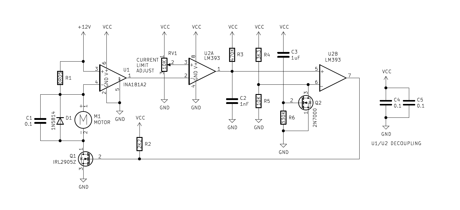
In the above circuit, the MOSFET switching the motor (Q1) can only ever be on or off, eliminating any switching loss during current limiting scenarios. The output from the INA181 is compared against a reference set by RV1, generating an digital output from U2A, which then discharges C2. The re-charging of C2 at U2B’s non inverting input results in a small delay, effectively generating a PWM.
- The “off” period is fixed.
- The “on” period varies depending on the degree of the overload.
- If there is no overload, the motor is on 100%.
Using a 555 timer in an astable configuration to generate the “off” period instead of U2B/C3/R3/R4/R5 would be quite a bit cleaner but that’s a whole lot of extra components.

Also present in this circuit is a “hold off” facility comprised of C3, R6 and Q2. This allows the motor to draw more current for about 300ms after power-on by lowering the reference voltage at U2B to zero. These components can be omitted if this isn’t required.
There’s plenty of scope for tuning this circuit, i.e. by changing the values of C2, R3, R4 and R5. Shown are the values I used in my application which worked fairly well.
Calculating the current limit
![\[I_L_I_M_I_T = \frac{R_S_E_N_S_E \times GAIN}{\frac{RV1_H}{RV1_L+RV1_H} \times V_C_C}\]](https://www.mattmillman.com/wp-content/ql-cache/quicklatex.com-a46df300d740573053b56d079936537d_l3.png "Rendered by QuickLaTeX.com")
- Ilimit: The motor limit current.
- Rsense: Value of the current sense resistor R1. 0.05 in my example.
- RV1h: The resistance between the potentiometer wiper and high (VCC) terminal.
- RV1l: The resistance between the potentiometer wiper and the low (GND) terminal.
- VCC: (volts). 5V in my example.
- GAIN: Gain of the INA181. 50 in my example. The gain is fixed at 50 for the INA181A2 Others variants are available but not too easy to come by.
Therefore, all of the circuits I’ve shown here limit the current to the motor to 1 A when RV1 is at the centre click.
Latched circuit (default state: off)

In this example the comparator drives an S/R latch. U3D and U3A are the latch, and U3C/U3D/C3/R4 are an extension to it ensure that it powers up in a known state – “off” in this example.
Once the current limit is hit (or after power-on) the motor is powered off until manually re/started by pressing the “start motor” button (or in my case, by a μC). Pressing this button also resets the 300ms delay circuit comprised of Q2, R2 and C2 allowing the motor to spin up without re-triggering the current limit.
Latched circuit (default state: on)
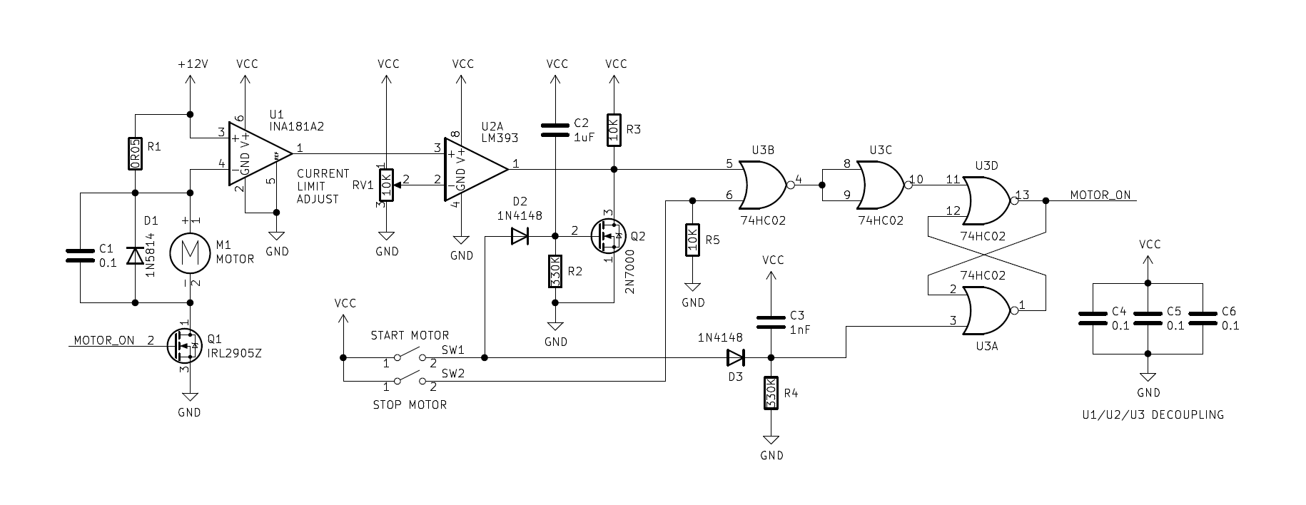
Same as the above but motor will power on when the circuit is powered up.
Posted in Circuit snippets